Innotech network diagram, 1 overview – Innotech Maxim User Manual
Page 42
MAXIM Installation Instructions
Page 42
© Mass Electronics Pty Ltd 2011
Edition 2.0 dated 20/11/2013
4-1 Overview
As mentioned in the
chapter, with the exception of the MAXIM I controller, all
other MAXIM Series controllers can be installed on a primary or a sub system network depending on
your specific model.
Installing a MAXIM Series controller on a network provides the ability to share data among all
controllers and devices on that network. Additionally it also provides the ability for the MAXIM Series
controllers to communicate with the Innotech iComm communication software, adding advanced
Supervisory Control and Data Acquisition (SCADA) functionality.
The MAXIM Series controllers utilise RS485 balanced (differential) communications when installed
on a network. Factors such as the type of network, cable distance, and single or multiple network
installation factors must be considered when carrying out a network installation.
An optional Ethernet port is also available on the Sub System Gateway (IG01), and MAXIM Series II, III,
and 1010 controllers for TCP/IP connectivity to your Local Area Network (LAN).
The MAXIM Series controllers have the flexibility to be installed in a wide range of applications.
Although it is not possible to cover all installation situations that may be encountered, following
some general guidelines and instructions will help to ensure the optimum installation for your
particular situation. Therefore please refer to th
or complete details and information on performing a network installation with
MAXIM Series controllers.
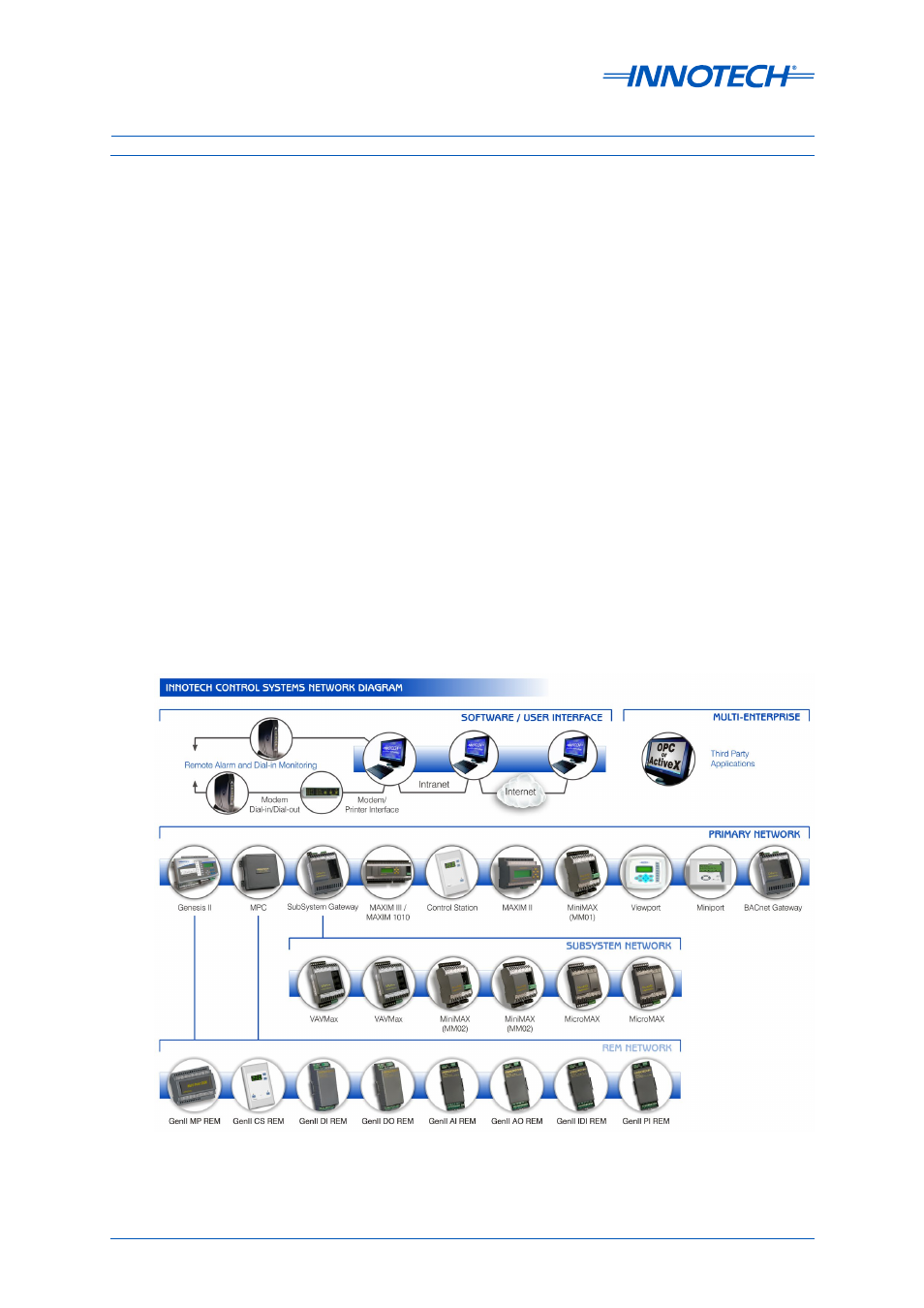
A general network diagram of Innotech hardware is illustrated in Figure 4-1 below.
Figure 4-1: Innotech Network Diagram