Document structure – Innotech Maxim User Manual
Page 11
Page 11
MAXIM Installation Instructions
© Mass Electronics Pty Ltd 2011
Chapter 1 – Preliminary Information
1-1.2 Terminology used in this manual
In order to simplify the instructions, common terminology and references to other Innotech products
are used throughout this manual. A brief description of some of the terminology is provided in this
section.
Net comms communication is the primary means of communication between Innotech hardware and
iComm software.
Global comms communication is a means of sharing data among different Innotech controllers and
devices to carry out different functions.
Human Machine Interface (HMI) provides direct access for complete control and operation of various
Innotech controllers. The HMI basically consists of the Liquid Crystal Display (LCD) and the keypad for
direct interaction with the controllers.
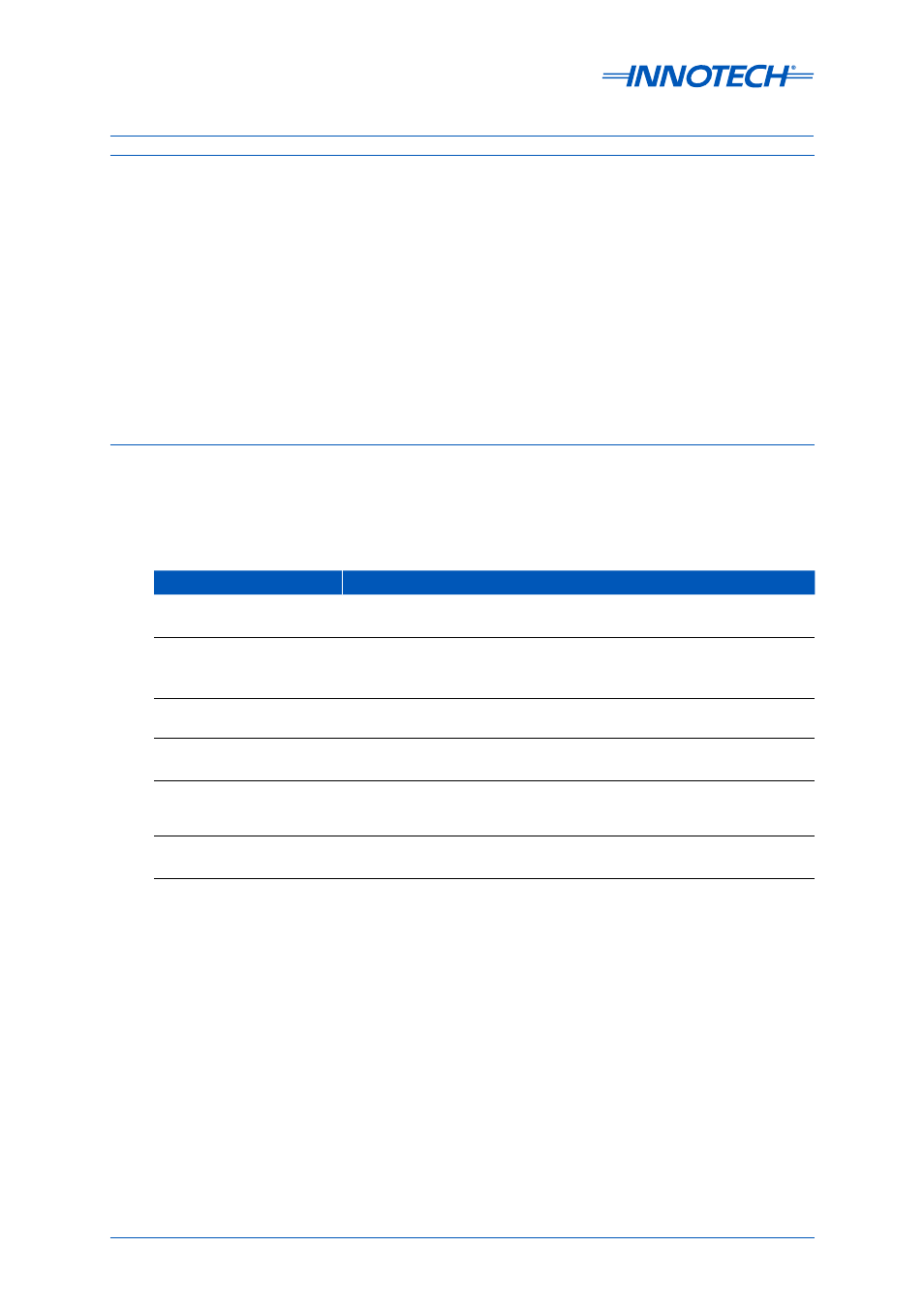
1-1.3 Document layout
This technical manual consists of the following sections with a brief description of each section:
Chapter
Description
Chapter 1 - Preliminary
Information
This chapter contains general information such as general safety
considerations and an overview of the MAXIM Series controllers.
Chapter 2 - Mechanical
Installation
This chapter contains information such as physical descriptions of
the controllers, mounting dimensions, and mechanical installation
guidelines.
Chapter 3 - Electrical
Installation
This chapter contains electrical wiring information and instructions.
Chapter 4 - Network
Installation
This chapter provides a general network diagram and reference to the
Chapter 5 - Commissioning
This chapter provides instructions for post-installation inspection of
the MAXIM System, and initial setup of the various units that comprise
the system.
Appendix A - Using the
CT01 Commissioning Tool
The Appendix provides instructions on using the CT01 for configuring
MAXIM Series controllers.
Table 1-1:
Document Structure