Innotech Maxim User Manual
Page 30
MAXIM Installation Instructions
Page 30
© Mass Electronics Pty Ltd 2011
Edition 2.0 dated 20/11/2013
3-3.1.3 Analogue Outputs
The analogue outputs can be configured with MAXCon software to either heat valve mode or variable
mode to suit your requirements. Each analogue output has a signal terminal (+) and a shared Com
terminal (–). As illustrated in the connection details in Figure 3-1, the + terminal is the active signal,
and the Com terminal is the signal reference of 0V, which also can be referred to as ground.
It must be noted that on MAXIM Series I and II controllers only AO1 and AO2 can be configured to heat
valve mode. However on MAXIM Series III all 8 Analogue Outputs can be configured to heat valve
mode.
When an analogue output is configured to heat valve mode, the output is a Pulse Width Modulated
(PWM) signal of 0 or 10V DC with a maximum current rating of 5m A. When an analogue output is
configured to variable mode, the output is an analogue voltage signal varying from 0 to 10V DC with a
maximum current rating of 5m A.
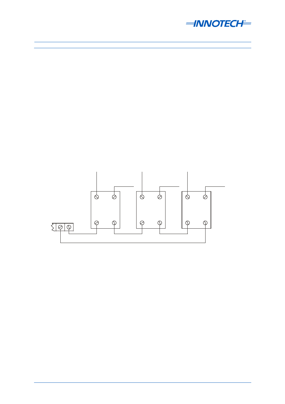
When an analogue output is configured as a PWM signal in heat valve mode, up to three Solid State
Relays (SSR) connected in series may be used on each analogue output channel, as illustrated in
Figure 3-6 below. The SSRs must be capable of a trigger voltage of 3 to 32V DC and zero switching.
1
2
3+ve
4
1
2
3+ve
4
1
2
3+ve
4
+
-
ANALOGUE
OUTPUT
TERMINALS
TO
HEATERS
TO
HEATERS
TO
HEATERS
L1
L2
L3
If up to 6 SSRs are to be wired in series, you can use the Analogue Output as 0 to 10V DC modulating
in conjunction with the Innotech Heat Valve (IHV) module. Please refer to the following datasheets
for more information on IHVs:
• DS3.31 for IHV Heat Valves
• DS3.32 for IHV42 Heat Valves
Figure 3-6: Analogue Output Driving Multiple Solid State Relays