Heading1 - 5.4 relay connections on the i/o board, Heading1 - 5.5 desiccant pack, 4 relay connections on the i/o board – In-Situ Con TROLL PRO Installation Manual (purchased before 10 May 2012) User Manual
Page 26: 5 desiccant pack
26
Input/Output Connections
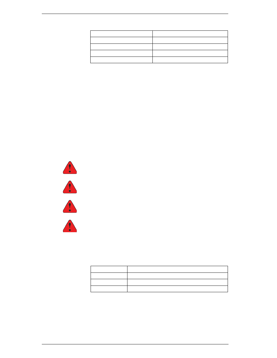
3. Connect the stripped and tinned, twisted-pair shielded, 24-12 AWG, 4-20
mA wires to the terminal strip and Protective Earth (ground) as follows:
4. Connect the wires at the device end. Do not ground the device at both
ends of the cable.
5. Replace the controller lid and tighten screws.
6. Reconnect power to the device.
5.4
RELAY CONNECTIONS ON THE I/O BOARD
Please note that the DC and AC models have different types of relays
available! All relay connections are unpowered relay NC & NO contact
connections only.
DC Models
Low voltage relays are available through the I/O board only.
AC Models
Low voltage relays are available through the I/O board.
High voltage relays are available through the AC board.
Danger
Do not connect high voltage circuits (>50 V) to the terminal
connectors on the I/O board!
Danger
Make sure that power to the instrument is disconnected
before making any wiring connections.
Danger
Ne pas connecter les circuits a haute tension (plus de 50 V)
aux bornes de connexion sur la carte entrées/sorties!
Danger
Débrancher toute alimentation à l'appareil avant de
connecter les fils.
1. Disconnect power to the instrument.
2. Use a Phillips screwdriver to remove the controller lid.
3. Connect the stripped and tinned relay wires to the terminal strip as
follows:
4. Replace the controller lid and tighten screws.
5. Reconnect power to the device.
5.5
DESICCANT PACK
Before closing the controller box, place the 5-inch desiccant pack (Cat. No.
0087630) inside the controller, being careful not to disturb any wiring.
LOOP2–
To negative (-) end of customer-supplied device
LOOP2+
To positive (+) end of customer-supplied device
LOOP1–
To negative (-) end of customer-supplied device
LOOP1+
To positive (+) end of customer-supplied device
Green Earth Ground screw (Figure 21) Shielded wire (silver color)
GND
Signal ground
COM1 (or COM2)
Common
NC1 (or NC2)
Normally closed
NO1 (or NC1)
Normally open