Chapter 5, Inpu, Input/output connections – In-Situ Con TROLL PRO Installation Manual (purchased before 10 May 2012) User Manual
Page 23: Input/output connections 23, Requires stripped and tinned ruggedcable, System requires stripped and tinned ruggedcable
Input/Output Connections
23
Chapter 5
Input/Output Connections
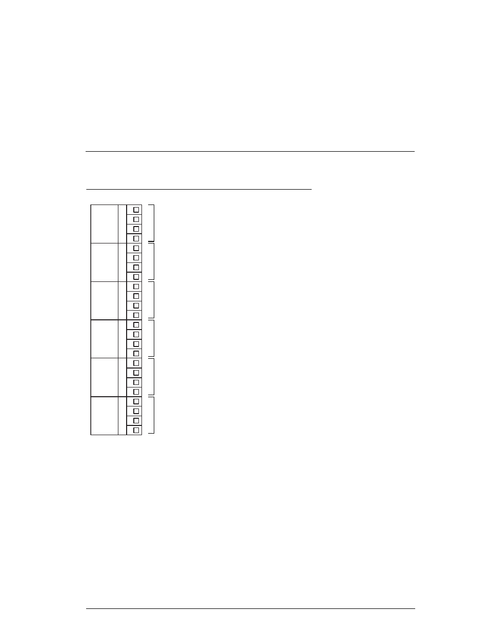
The Input/Output board is shown in Figure 20. It is located inside the
enclosure on the left side.
FIGURE 20. Input/Output board and required wire types
P
L
C
P
R
O
B
E
A
P
R
O
B
E
B
4
/
2
0
m
A
R
E
L
A
Y
1
R
E
L
A
Y
2
GND
485A-
485B+
POWER
GND
485A-
485B+
POWER
GND
485A-
485B+
POWER
LOOP2-
LOOP2+
LOOP1-
LOOP1+
GND
COM1
NC1
NO1
GND
COM2
NC2
NO2
Requires stripped and tinned RuggedCable
®
system
Requires stripped and tinned RuggedCable
®
system
Requires 24-12 AWG cable
Requires 24-12 AWG cable
Requires 24-12 AWG cable
Requires 24-12 AWG cable. PLC connections typically consist of the following:
• Con TROLL PRO AC models: 24 VDC output to power accessories
• Con TROLL PRO DC model: 9-36 VDC inputs to power the controller (required)
This manual is related to the following products: