Ridder control, Pt controller – Hired-Hand RollSeal Rollup Curtains: Ridder Motor Control User Manual
Page 9
4801-5081
Ridder Motor Control
7
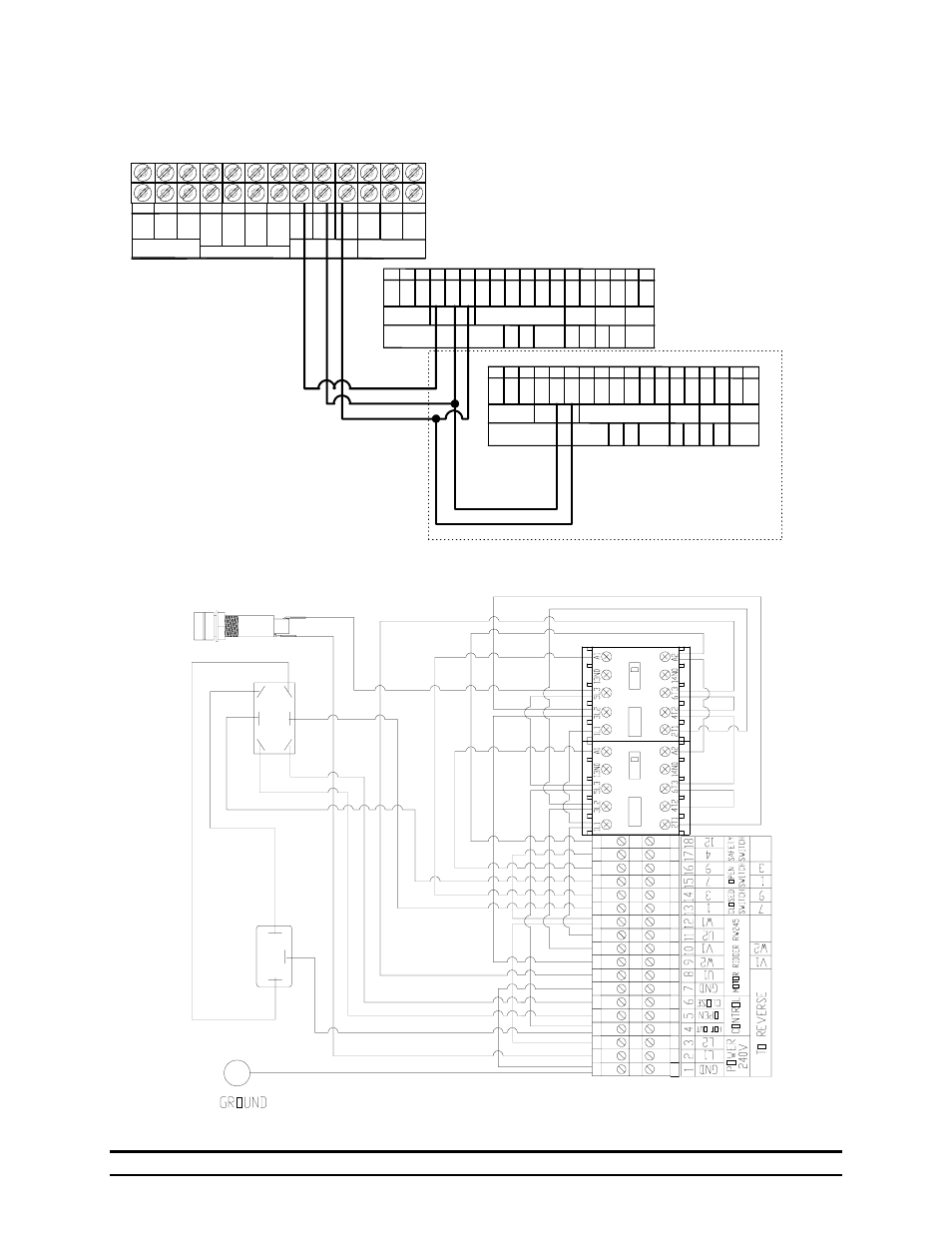
7.6 Ridder Controller to a PT controller
7.7 Exploded View Diagram
1
GN
D
9
12
10
8
7
6
5
4
3
2
11 12 13 14 15 16 17 18
L1
L2
HO
T
OP
E
N
CL
O
SE
GN
D
U1
W2
V1
U2
W1
1
3
7
9
4
CONTROL MOTOR RIDDER RW245
OU
T
P O W E R
240V
SWITCH
CLOSED
SWITCH SWITCH
OPEN
SAFETY
V1
W2
3
1
9
7
TO REVERSE
1
GN
D
9
12
10
8
7
6
5
4
3
2
11 12 13 14 15 16 17 18
L1
L2
HO
T
O
PEN
CLO
SE
GN
D
U1
W2
V1
U2
W1
1
3
7
9
4
CONTROL MOTOR RIDDER RW245
OU
T
P O W E R
240V
SWITCH
CLOSED
SWITCH SWITCH
OPEN
SAFETY
V1
W2
3
1
9
7
TO REVERSE
Ridder Control
Ridder Control
Note: Connecting multiple Ridder
Controls to one control source parallel
open and close connections as shown
for each additional controller.
Warning: All controllers must also
have the same power supply
connected in parallel to L1 and L2.
1
2
3
4
5
6
7
8
9
10
11
12
13
OP
EN
CL
O
S
E
RE
D
BL
AC
K
WH
IT
E
GR
E
E
N
Hot
IN
Thermostat/Control
L1
Power Supply
L2
GND
OP
EN
CL
O
S
E
Hot
IN
UNIT 1
UNIT 2
(O
pen
)
(G
ro
u
n
d
)
(C
lo
s
e
)
(
C
o
mmo
n
)
PT Controller
- RollSeal Rolling Dampers (5 pages)
- RollSeal Rollup Curtains: RollSeal Motor Controls (16 pages)
- RollSeal Rollup Curtains: ROLLUP CURTAIN SYSTEM Rev 11-05 (38 pages)
- RollSeal Rollup Curtains: ROLLUP CURTAIN SYSTEM Rev 12-07 (26 pages)
- RollSeal Sidewall System (Curtain): SideWall Curtain (38 pages)
- RollSeal Sidewall System (Curtain): Wiring Diagram And Limit Switches (2 pages)
- RollSeal Sidewall System (Curtain): Floating Hook & Loop Assembly (2 pages)
- Light Traps: Light Trap Fan Unit (2 pages)
- Light Traps: Light Trap Adapter Kit (2 pages)
- Light Traps: 54x54 Light Trap Air Inlet (2 pages)
- Light Traps: 7x44 - 8x44 Light Trap Air Inlet (1 page)
- Light Traps: Light Trap Vent Box Installation (1 page)
- Light Traps: Installing Continuous Light Trap (6 pages)
- Light Traps: Installing Light Trap for Fan (4 pages)
- Light Traps: Light Trap Fan Unassembled (4 pages)
- Baffles, Vents, & Inlets: VENT DOORS Installation (2 pages)
- Baffles, Vents, & Inlets: GRAVITY VENT DOOR Installation (2 pages)
- Baffles, Vents, & Inlets: SINGLE CEILING INLET (2 pages)
- Baffles, Vents, & Inlets: 24 & 36 Chimney Vent (12 pages)
- Baffles, Vents, & Inlets: Vent Kit for Generation Structures (8 pages)
- Baffles, Vents, & Inlets: QUAD CEILING INLET (2 pages)
- Baffles, Vents, & Inlets: Ridge Vent Assembly Instructions (2 pages)
- Baffles, Vents, & Inlets: Installing Ceiling Inlets (2 pages)
- Tunnel Doors (16 pages)
- Circulation and Stir Fans: MEGA-FLOW FANS (See Reverse Side for Framing Formats) (2 pages)
- Circulation and Stir Fans: MEGA-FLOW 24 INCH ORIFICE STIR FANS (2 pages)
- Circulation and Stir Fans: MEGA-FLOW ORIFICE FANS (2 pages)
- Circulation and Stir Fans: Post Mount Assembly For 52 Orifice Fans (4 pages)
- Circulation and Stir Fans: Funnel Flow Fan (1 page)
- Circulation and Stir Fans: MEGA FLOW FANS Round Dairy Fan (2 pages)
- Circulation and Stir Fans: 48 MEGA FLOW (2 pages)
- Circulation and Stir Fans: 48 MEGA FLOW Galvanized (2 pages)
- Circulation and Stir Fans: MEGA FLOW 36 (91 cm) Fan Housing (2 pages)
- Circulation and Stir Fans: 48 MEGA FLOW Fan Housing (2 pages)
- Circulation and Stir Fans: 52 Orifice Fan HSP Conversion Kit (2 pages)
- Circulation and Stir Fans: HAF Fan Mounting Bracket Installation (2 pages)
- Circulation and Stir Fans: POST MOUNT KIT ASSEMBLY (2 pages)
- Circulation and Stir Fans: MEGA FLOW Motor Replacement 36 (91 cm) Fan Housing (2 pages)
- Mega Flow Panel Fans: Econo-Flow 48 Belt Drive Panel Fan (2 pages)
- Mega Flow Panel Fans: Power Cord Installation (2 pages)
- Mega Flow Panel Fans: BELT TENSIONER 48 Mega Flow Fan (1 page)
- Funnel Flow Fans: Belt Tensioner (2 pages)
- Funnel Flow Fans Rev 12-03 (2 pages)
- Funnel Flow Fans Rev 10-98 (1 page)