Step 10: cabling, Step 11: cable connections, Step 12: cover reinstallation – IEI Integration RACK-2100G User Manual
Page 9: Chassis mantenance, Warning
RACK-2100G QIG
IEI Technology Corp. Page 9
S
TEP
9.2:
FDD/HDD
AND
O
PTICAL
D
RIVE
B
RACKET
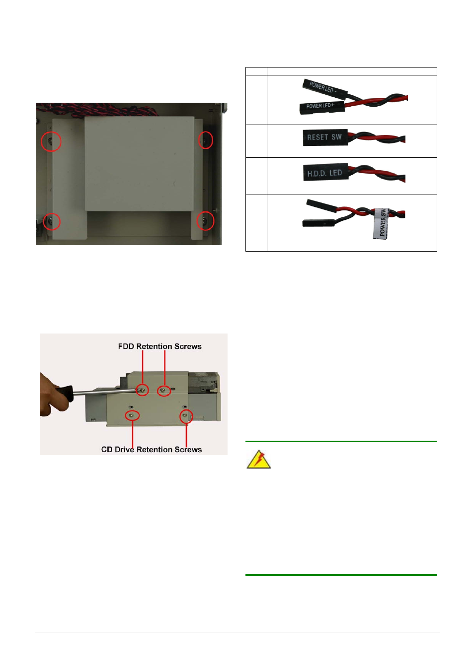
The main drive bracket can support one FDD or HDD and one
optical drive. Follow the steps below to install the drives.
Step 1:
Remove the retention screws that connect the drive
bracket to the chassis.
Figure 26: Main Drive Bracket Retention Screws
Step 2:
Mount the drives into the bracket. Make sure the power
connectors and the IDE/SATA connectors are at the rear
of the bracket.
Step 3:
Both the FDD/HDD and 5.25” optical drive are secured
with four retention screws, two on each side of the
bracket.
Figure 27: FDD/HDD and Optical Drive Retention Screws
Step 4:
Remount the main drive bracket into the chassis and
reinsert the previously removed retention screws.
Step 0:
STEP 10: CABLING
The front bezel of the RACK-2100G/GR has the following
items:
o
1 x Power LED
o
1 x HDD LED
o
1 x Power switch
o
1 x Reset button
These items are connected to the CPU card with cables. To
connect these items to the CPU card, refer to the technical
documentation that came with the CPU card. The
connectors provided with the chassis are listed below.
No.
Name
1
Power LED cable
1
Reset Switch cable
1
HDD LED cable
1
Power switch cable
Table 4: Chassis Front Panel Connectors
STEP 11: CABLE CONNECTIONS
Follow the steps below to connect the power and ribbon cables.
Step 1:
Connect the power cables from the PSU to the
backplane, full-size CPU card, HDD, FDD, cooling fan
and CD drive power connectors.
Step 2:
Disk drive interface connectors must be connected to
the CPU card.
Step 0:
STEP 12: COVER REINSTALLATION
Reinstall the chassis top cover after completing the above
procedures. To do this, slide the cover back over the chassis and
reinsert the previously removed retention screws.
CHASSIS MANTENANCE
WARNING:
1. Never attempt to remove the external panels or access any
internal components of the chassis while it is connected to a
power source. Always be sure to turn off and disconnect the
chassis from all power sources before attempting to access
the internal components. Failure to do so may seriously injury
the user or cause irreparable damage the internal components
of the chassis.
2. Take anti-static precautions whenever carrying out
maintenance on the system components. Failure to take
anti-static precautions can cause permanent system damage.