Step 6: cpu card installation, Step 7: pci/isa expansion card installation, Step 8: backplane bracket reinstallation – IEI Integration RACK-2100G User Manual
Page 7
RACK-2100G QIG
IEI Technology Corp. Page 7
STEP 6: CPU CARD INSTALLATION
A CPU card must be installed into the backplane before the bracket
can be reinstalled into the chassis. Follow the steps below to install a
CPU card.
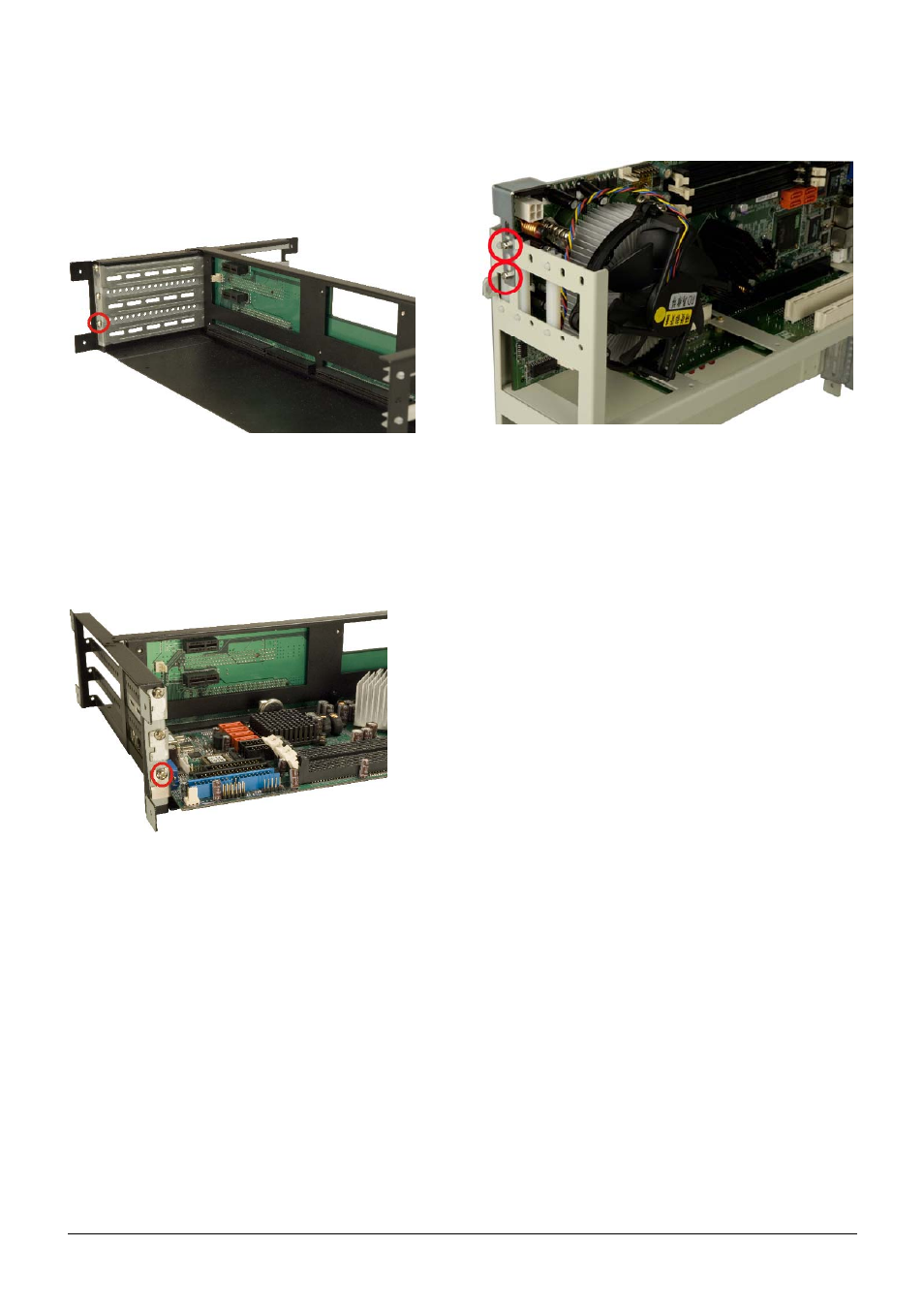
Step 1:
Remove the slot cover at the rear of the backplane
bracket. To do this, remove the slot cover retention
screw at the side of the slot cover.
Figure 18: Remove the Slot Cover Retention Screw
Step 2:
Slide the CPU card into the CPU socket on the
backplane. Make sure the CPU card also slides into the
corresponding plastic guide.
Step 3:
Reinsert the previously removed slot cover retention
screw to secure the CPU card.
Figure 19: Secure the CPU Card to the Backplane Bracket
Step 4:
To secure the CPU card in place, press the rubber end
of the PCI/ISA card shock absorber against the top of
the CPU card and align the shock absorber screw holes
with the backplane bracket screw holes.
Figure 20: Insert Two Shock Absorber Retention Screws
Step 5:
Insert two retention screws to secure the shock
absorber to the backplane bracket.
Step 0:
STEP 7: PCI/ISA EXPANSION CARD
INSTALLATION
The RACK-2100G/R supports up to five PCI/ISA expansion cards. If
a PCI expansion card or an ISA expansion card is being installed
please follow the instructions below.
Step 1:
Remove the slot cover at the back of the backplane
bracket. To do this, remove the slot cover retention
screw on the side of the slot cover.
Step 2:
Slide the PCI/ISA expansion card into a reserved
PCI/ISA socket on the backplane.
Step 3:
To secure the PCI/ISA expansion card, reinsert the
previously removed slot cover retention screw.
Step 0:
STEP 8: BACKPLANE BRACKET
REINSTALLATION
After the backplane, CPU card and any expansion cards have been
secured to the backplane bracket, the backplane bracket can be
reinstalled into the chassis.
Step 1:
Mount the backplane bracket in the chassis. Make sure
the retention screw holes of the bracket are aligned with
the screw holes in the base and at the back of the
chassis.
Step 2:
Secure the backplane bracket to the chassis with the six
previously removed retention screws. Insert two
retention screws on the base of the chassis and four
retention screws at the rear of the chassis.
Step 0: