Insteon setup, Insteon controllers, responders and links, Configure insteon settings – INSTEON Micro Open/Close - 2444-222 (US), 2444-422 (EU), 2444-522 (AUS/NZ) Manual User Manual
Page 11: Make micro module a responder (set button), Make micro module a responder (switch)
Page 11 of 21
2444-222/2444-422/2444-522 - Rev: 2/24/2014 9:10 AM
This setting is only adjustable via software or a central controller. Micro module will beep every time its connected
switch is tapped or a button is pressed.
INSTEON Setup
Some products have subtle differences in their setup procedures. Please refer to the other devices’ owner’s manuals
for details.
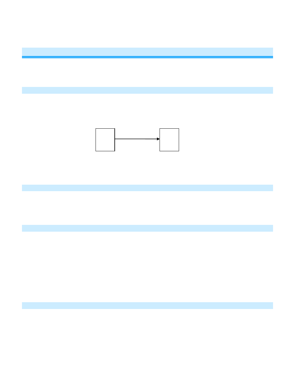
INSTEON Controllers, Responders and Links
• The INSTEON “transmitter” is called a controller
• The INSTEON “receiver” is called a responder
• The association between the controller and responder is called a link
Note that a link is one way. If you wish to have control “the other way,” simply add a link “the other way.”
Configure INSTEON Settings
Most Micro module links and settings can be configured locally—during installation with the module’s Set button or
after installation using the switch connected to the module.
All Micro module settings can be managed remotely via software (sold separately).
Make Micro Module a Responder (Set button)
Note: you must perform these steps before reinstalling the wall switch or fixture.
1) Press and hold controller Set button until it beeps
Controller LED will start blinking
You will have four minutes to complete the next steps before linking mode times out
2) Adjust load connected to Micro module to desired level (up or down)
3) Press and hold Micro module Set button until it double-beeps
Controller will double-beep and its LED will stop blinking
4) Test link by tapping controller button on and off
Load connected to Micro module will respond appropriately
Make Micro Module a Responder (Switch)
1) Press and hold controller Set button until it beeps
Controller LED will start blinking
You will have four minutes to complete the next steps before linking mode times out
2) Adjust load connected to Micro module to desired level (up or down)
3) Quickly tap switch connected to Micro module exactly five times in less than four seconds. (If using a latching or
dual momentary switch, alternate switch directions: up-down-up-down-up or down-up-down-up-down.) After
tapping switch, wait two seconds.
Controller
Responder
Link