Ti-2 connections – Biamp LTR User Manual
Page 14
14
AudiaFLEX Optional Telephone Interface TI-2
Telecom Connection Instructions
CAUTION: These instructions are for use by qualified personnel only. To reduce the risk of
electrical shock, do not perform any servicing other than that contained in the operating
instructions, unless you are qualified to do so.
Connections to this device must be installed by qualified, trained personnel. Connections to
the telephone network must be made with #26 AWG solid copper wire for continued safety.
Wire shall be stripped to 9.0 mm or 0.35".
T
R
T
R
T
telephone only
R
T
R
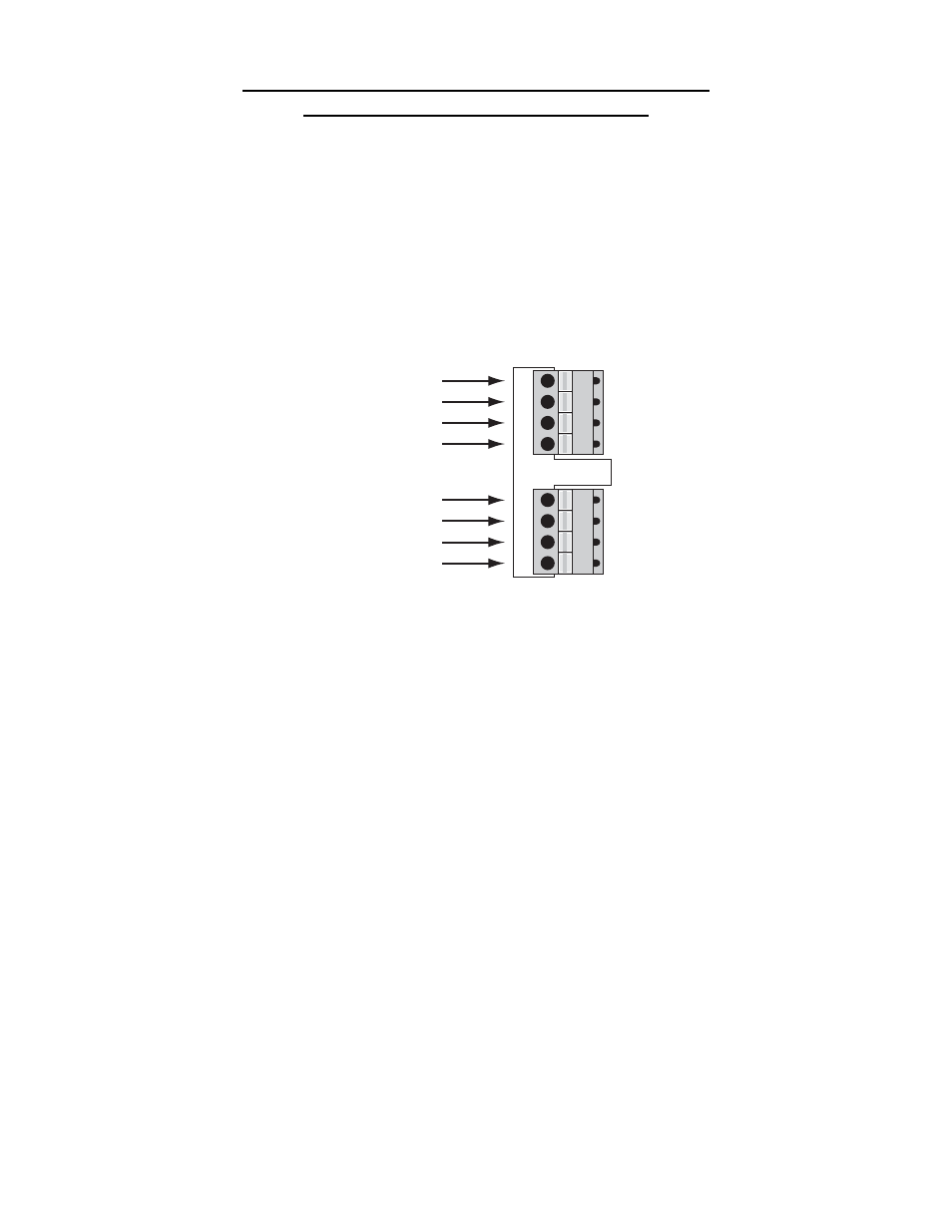
Line 1 TIP
Line 1 RING
Line 1 TIP
Line 1 RING
TI-2 connections
Line 2 TIP
Line 2 RING
Line 2 TIP
Line 2 RING
The TI-2 utilizes 'spring cage' type connectors. To assure reliable connection, it is important
that only a single wire conductor be used in each cavity of the connectors. Use a small
screwdriver or other such implement to depress the orange key adjacent to the cavity while
inserting the wire. Release the key to capture the wire.
Each of the TI-2's independent phone lines has a separate connector. This allows one to be
disconnected for diagnostics or wiring, without disrupting the other. Each line has two parallel
connections for TIP and two parallel connections for RING. This allows another device (such
as a local telephone or answering machine) to be connected in parallel with the telephone line,
via the TI-2. When connecting wire to the TI-2 connectors maintain a consistent twist rate in
the wires as close to the TI-2 as possible. Always use #26 AWG solid copper wire stripped to
0.35 inches (9mm) for continued safety.