4 input power failure-load on battery, Figure 56 input power fail-load on battery, Input power failure—load on battery – Liebert 1000kVA User Manual
Page 83: Figure 56 input power fail—load on battery, 4 input power failure—load on battery, Scct, Operation 77
Operation
77
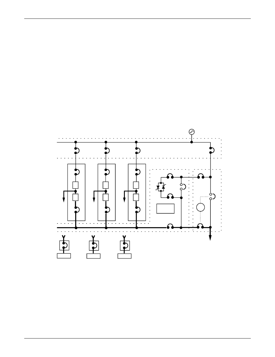
3.3.4 Input Power Failure—Load on Battery
If the utility AC power source fails or is outside the acceptable range, the battery plant becomes the
power source for the UPS module inverters. The UPS system continues to supply power to the critical
load and also to the controls of the UPS modules and the SCC.
You can use the Battery Time screen at the UPS modules to monitor the present battery voltage com-
pared to the shutdown value. The length of time the battery can sustain the load depends on the size
of the load and the size and condition of the battery plant. The battery plant is usually large enough
to supply a 100% rated load for 15 minutes.
Alarm messages that indicate battery status are Battery Discharge, Low Battery and Battery Shut-
down. The voltage limits for these alarms are displayed on the UPS module Alarm Limit Settings
screen. These limits were selected for your installation by Liebert Global Services during initial start-
up.
The battery block in the UPS module Monitor/Mimic Display indicates Charge or Discharge and the
current in Amperes. Maximum battery discharge current ranges from 326 amps (for 150kVA) to 1620
amps (for 750kVA). Refer to the separate Installation Manual or drawings for specific data on your
system.
Figure 56 Input power fail—load on battery
BIB
SKRU
MIB
MBB
#2
UPS
CB1
#1
UPS
CB1
System
Controls
#3
UPS
CB1
RIB
RIB
RIB
BFB
Output
SBB
SBS
I
CB2
I
I
CB2
CB2
R
R
R
SCCT
SCCT
(can accommodate up to 6 UPS modules)
To Critical Load
Battery
MBD
Battery
MBD
Battery
MBD