Mitsubishi Motors DS5000TK User Manual
Page 19
USER’S GUIDE
050396 18/173
19
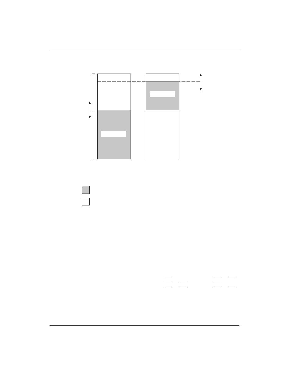
PARTITIONABLE MEMORY MAP FOR DS5001/DS5002 SERIES Figure 4–5
FFFFh
0000
PROGRAM
DATA
LEGEND:
BYTE–WIDE
BUS ACCESS
BYTE–WIDE
BUS ACCESS
PARTITION
ADDR.
ПП
ПП
= EXPANDED BUS ACCESS ON PORTS 0 AND 2
BYTE–WIDE ACCESS
(NONVOLATILE RAM)
=
PES=0
64K
RANGE
ADDRESS
MEMORY
MEMORY
The non–partitionable mode allows the maximum
amount of memory to be used on the Byte–wide bus. A
non–partitionable mode would be used because the
8051 architecture is restricted to a total of 64K program
and 64K data (without bank switching). This means that
if the maximum amount of either program or data (or
both) is needed, partitioning can not be done. The
DS5001/DS5002 series accommodates these situa-
tions with four selections of non–partitionable (PM=1)
memory control shown below. These are selected using
the Range bits when PM=1. Also note the MSEL signal.
This is a pin on DS5001/DS5002 series devices that
tells the processor whether multiple 32K RAMs or a
128K RAM is being used. When MSEL=0, a single 128K
device is used. It is not possible to partition the device
when MSEL=0, and the state of the partition bits will be
ignored. The four selections are as follows. The non–
partitionable memory map is shown in Figure 4–6.
Byte–wide bus segments begin at 0000h.
MSEL
RG1
RG0
PROGRAM
DATA
PROGRAM ACCESS
DATA ACCESS
1
0
0
32K
64K
1 @ 32K, CE1
2 @ 32K, CE3 and CE4
1
0
1
64K
32K
2 @ 32K, CE1 and CE2
1 @ 32K, CE3
1
1
0
64K
64K
2 @ 32K, CE1 and CE2
2 @ 32K, CE3 and CE4
0
1
1
64K
64K
1 @ 128K X 8, for both program and data