Step 10: install globe a, Step 11: operation of remote control – Hunter Fan 41597-01 User Manual
Page 6
41597-01 12/21/2002 5 © 2002 Hunter Fan Company™
41597-01 12/21/2002 6 © 2002 Hunter Fan Company™
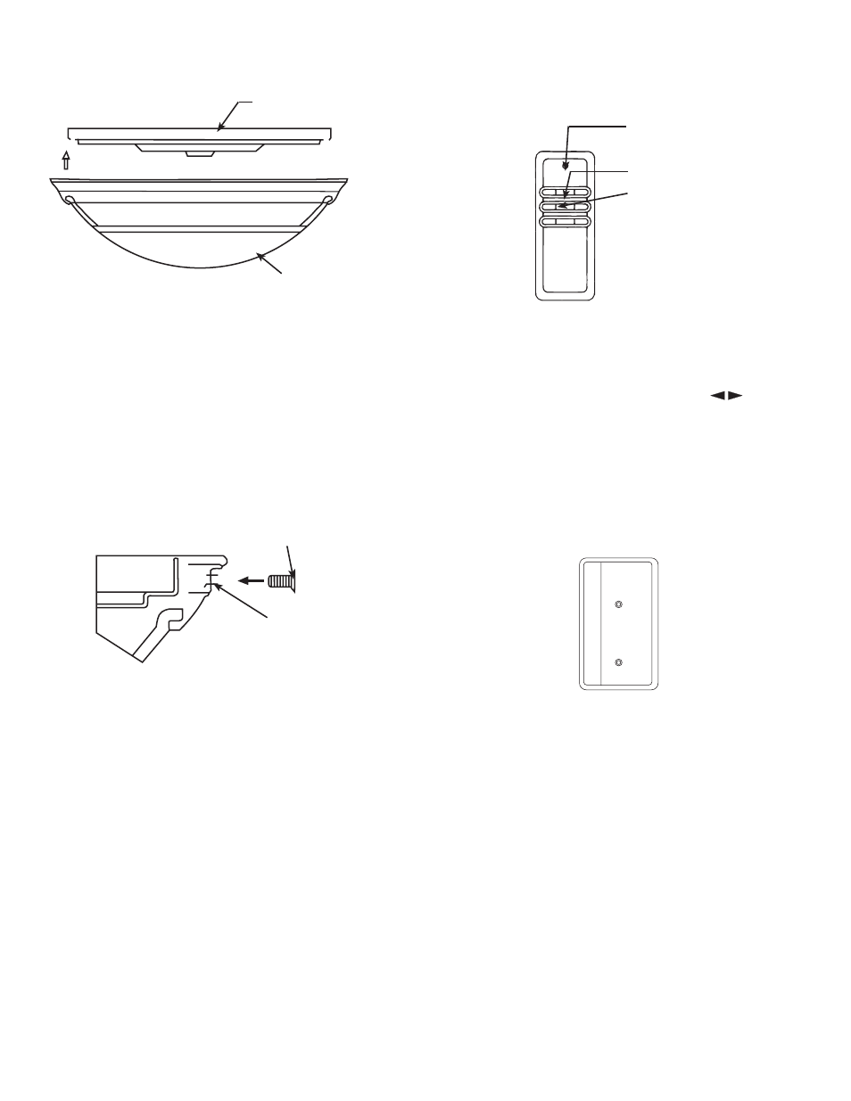
Step 10: Install Globe
A.
Install the glass globe assembly to fixture fitter. See Figure 10.
Lift the globe assembly until it’s free to rotate in either direction.
Rotate the globe assembly until the (3) screw clearance holes in
the globe trim line up with the matching threaded holes in the
fixture fitter. See Figures 10 and 10A.
Secure the globe assembly to the fitter using (3) screws found in
sack parts. See Figure 10A.
Tighten all (3) assembly screws.
CAUTION: Failure to securely tighten the (3) assembly screws
could result in the globe assembly falling.
Step 11: Operation of Remote Control
Operating Instructions: The hand-held transmitter has individ-
ual buttons for control of the light, for controlling the fan speeds,
for turning the fan off, and .for reversing. See Figure 11.
NOTE: Be sure to install a fresh battery. Check for weak battery
if fan fails to operate properly.
The fan may be started by pressing one of the buttons marked “1,”
“2,” or “3,” for high, medium, or low, respectively. Pressing the
button marked “FAN” will turn the fan off. The button is
for reversing. When this button is pushed the fan will reverse its
direction of rotation.
Wall Mount: A holder is supplied with the transmitter which
can be mounted to a convenient location on a wall. The holder
will help prevent misplacement of your transmitter by providing
a permanent receptacle. See Figure 11A.
If desired, the holder can be mounted directly over the wall
switch.
FIGURE 11
INDICATOR
LAMP
LIGHT
FAN
FIGURE 11A
HOLDER
Figure 10
FIXTURE FITTER
GLOBE ASSEMBLY
Figure 10A
ASSEMBLY SCREW
CLEARANCE HOLE