Refrigeration piping and line sizing, Figure 6. refrigeration piping diagrams, 10 door vault cooler – Heatcraft Refrigeration Products II User Manual
Page 7: Vault ice merchandiser, 10° vault storage freezer
7
Refrigeration Piping And Line Sizing
Refrigeration Piping And Line Sizing
The system as supplied by Heatcraft, was thoroughly cleaned and dehydrated at the factory. Foreign matter may
enter the system by way of the evaporator to condensing unit piping. Therefore, care must be used during
installation of the piping to prevent entrance of foreign matter. Install all refrigeration system components in
accordance with applicable local and national codes and in conformance with good practice required for the
proper operation of the system. The refrigerant pipe size should be selected from the tables in Refrigeration
System Installation Manual, Part Number 25001201. The interconnecting pipe size is not necessarily the same
size as the stub-out on the condensing unit or the evaporator.
The following procedures should be followed:
(a) Do not leave dehydrated compressors or filter-driers on condensing units open to the atmosphere any longer
than is absolutely necessary.
(b) Use only refrigeration grade (ACR) copper tubing, properly sealed against contamination.
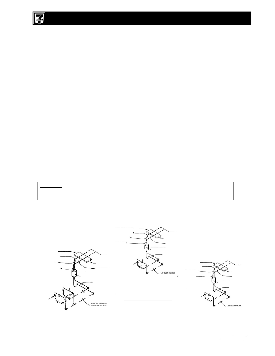
(c) Suction lines should slope 1/4” per 10 feet towards the compressor (in direction of flow).
(d) Suitable P-type oil traps should be located at the base of each suction riser to enhance oil return to the
compressor.
(e) For desired method of superheat measurement, a pressure tap should be installed in each evaporator
suction line in the proximity of the expansion valve bulb.
(f) When brazing refrigerant lines, an inert gas should be passed through the line at low pressure to prevent
scaling and oxidation inside the tubing. Dry nitrogen is preferred.
(g) Use only a suitable silver solder alloy on suction and liquid lines.
(h) Limit the soldering paste of flux to the minimum required to prevent contamination of the solder joint internally.
Flux only the male portion of the connection, never the female. After brazing, remove excess flux.
(i)
Remove temperature sensor attached to suction line on Beacon II systems before brazing of the solder joint
internally. Flux only the male portion of the connection – never the female. After brazing, remove excess flux.
(j)
Wrap expansion valves with wet rags during brazing to the liquid line.
CAUTION:
If the temperature gets too high, these components may be damaged. Heat absorbing
compounds or wet rags must be used to protect the expansion valve when brazing to the refrigerant
piping/line connections, and the suction line sensor must be removed per above instructions.
(k) Do not use “bull head” tees. This will cause oil return problems and can cause poor performance.
(l)
If isolation valves are installed at the evaporator, full port ball valves should be used.
7/8”
3/8”
1/2”
L
L
S
S
SLOPE DOWN TO UNIT
PITCH AWAY FROM UNIT
1/2” LIQUID LINE
1-1/8” SUCTION LINE
TO MCCU
UNIT ON ROOF
BRACE DOWN
EVERY 6.0 FT.
PITCH DOWN
TOWARD UNIT
ROOF PENETRATION BY OTHERS
(SEE ARCH. PLANS)
1/2” LIQUID LINE
BEACON
ELECTRIC
EXPANSION
VALVE
(TYP.)
FACTORY
MOUNTED
1-1/8” SUCTION LINE
INSULATED WITH 3/4”
WALL ARMAFLEX OR EQUAL
SLOPE DOWN TO UNIT
PITCH AWAY FROM UNIT
3/8” LIQUID LINE
SUCTION LINE
BEACON
ELECTRIC
EXPANSION
VALVE
(TYP.)
FACTORY
MOUNTED
3/8” LIQUID LINE
ROOF PENETRATION BY OTHERS
(SEE ARCH. PLANS)
PITCH DOWN
TOWARD UNIT
BRACE DOWN
EVERY 6.0 FT.
TO MCCU
UNIT ON ROOF
1/2” SUCTION LINE
INSULATED WITH 3/4”
WALL ARMAFLEX OR EQUAL
7/8”
1/2”
3/8”
S
S
S
L
PIPING DIAGRAM FOR THE
(R22) MEDIUM TEMPERATURE COOLER
REFRIGERATION SYSTEM
10 DOOR VAULT COOLER
NOT TO SCALE
PIPING DIAGRAM FOR THE
(R404a) LOW TEMPERATURE FREEZER
REFRIGERATION SYSTEM
VAULT ICE MERCHANDISER
NOT TO SCALE
PITCH AWAY FROM UNIT
SUCTION LINE
BEACON
ELECTRIC
EXPANSION
VALVE
(TYP.)
FACTORY
MOUNTED
3/8”
5/8”
S
S
L
5/8” SUCTION LINE
INSULATED WITH 3/4”
WALL ARMAFLEX OR EQUAL
3/8” LIQUID LINE
ROOF PENETRATION BY OTHERS
(SEE ARCH. PLANS)
PITCH DOWN
TOWARD UNIT
BRACE DOWN
EVERY 6.0 FT.
TO MCCU
UNIT ON ROOF
PIPING DIAGRAM FOR THE
(R404a) LOW TEMPERATURE FREEZER
REFRIGERATION SYSTEM
-10° VAULT STORAGE FREEZER
NOT TO SCALE
3/8” LIQUID LINE
SLOPE DOWN TO UNIT
Figure 6. Refrigeration Piping Diagrams