Warning, B. using offsets/returns, Table 5.2 – Heat & Glo Fireplace EXCLAIM-36T-C User Manual
Page 18
Heat & Glo • EXCLAIM-36C Woodburning Fireplace • 4013-093 Rev G • 08/06
18
B. Using Offsets/Returns
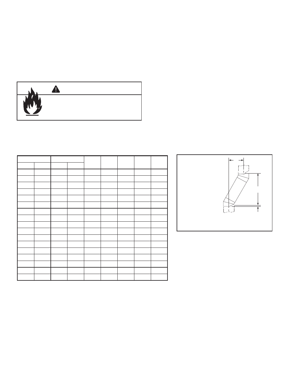
To bypass any overhead obstructions, the chimney may be
offset using a 30-deg (SL430) offset/return.
An offset and return may be attached together or a chimney
section(s) may be used between an offset and return.
Perform the following steps to determine the correct chim-
ney component combination for your particular installation:
•
Measure how far the chimney needs to be shifted to enable
it to avoid the overhead obstacle. See Figure 5.3. Use
dimension “A” to determine chimney section required to
achieve the needed shift.
• After determining the offset dimension, refer to Table 5.2
and
¿ nd the “A” dimension closest to but not less than the
distance of shift needed for your installation.
• The “B” dimension that coincides with the “A” dimension
represents the required vertical clearance that is needed
to complete the offset and return.
• Read across the chart and
¿ nd the number of chimney
sections required and the model number of those particular
chimney parts.
•
Whenever the chimney penetrates a
À oor/ceiling, a ceiling
¿ restop must be installed.
•
The effective height of the
¿ replace assembly is measured
from the base of the
¿ replace to the top of the starter collar.
See Dimensions in Section 12.
Table 5.2
A
B
1-1/4 in. (32 mm
OVERLAP
Figure 5.3
Chimney Offset/Return
Example: Your “A” dimension from Figure 5.3
is 14 1/2 in. (368 mm). Using Table 5.2 the
dimension closest to, but not less than 14- /2
in. (368 mm) is 14 5/8 in. (371 mm) using a
30° offset/return. It is then determined from
the table that you would need 33 in. (838 mm)
(Dimension “B”) between the offset and return.
The chimney components that best
¿ t your
application are two SL412s.
Fire Risk
• Draft will be restricted if offset/returns
greater than 30° are used.
WARNING
A
B
SL406
SL412
SL418
SL436
SL448
in.
mm
in.
mm
3-7/8
98
14-1/2
368
-
-
-
-
-
6-1/4
159
18-5/8
473
1
-
-
-
-
9-1/4
235
23-3/4
603
-
1
-
-
-
12-1/4
311
29
737
-
-
1
-
-
14-5/8
371
33
838
-
2
-
-
-
17-5/8
448
38-1/4
972
-
1
1
-
-
21-1/4
540
44-5/8
1133
-
-
-
1
-
23-5/8
600
48-3/4
1238
1
-
-
1
-
27-1/4
692
55-3/4
1416
-
-
-
-
1
29-5/8
752
59
1499
1
-
-
-
1
32-5/8
829
64-1/4
1632
-
1
-
-
1
35-5/8
905
69-1/2
1765
-
-
1
-
1
38
965
73-5/8
1870
-
2
-
-
1
41
1041
78-3/4
2000
-
1
1
-
1
44-5/8
1133
85
2159
-
-
-
1
1
47
1194
89-1/8
2264
1
-
-
1
1
50-5/8
1286
95-1/2
2426
-
-
-
-
2
Proper assembly of air cooled chimney parts results in an overlap of chimney joints of
1-1/4 in. (32 mm). Effective length is built into this table.
¨
¨