Hoshizaki SELF-CONTAINED CRESCENT CUBER L1F015102 User Manual
Page 12
9
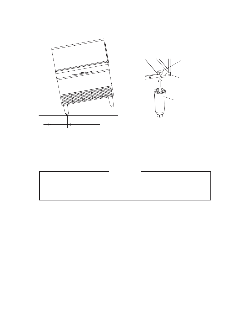
Fig. 2
Fig. 3
Tapped Hole
(Leg Mounting)
Base
from 6” (15.2 cm) to 7” (17.8 cm). Screw the legs tightly into the tapped holes in the
base (see Fig. 3). Handle the icemaker carefully not to damage the exterior.
F. Water Supply and Drain Connections
- See Figs. 4 and 5
CAUTION
To prevent damage to equipment, do not operate this icemaker when the
water supply is OFF, or if the pressure is below 10 PSIG (0.7 bar). Do not run
the icemaker until proper water pressure is reached.
* Water supply inlet is 1/2” female pipe thread (FPT).
* A water supply line shut-off valve and drain valve should be installed. A minimum of 3/8”
OD copper tubing is recommended for the water supply lines.
* Water supply pressure should be a minimum of 10 PSIG (0.7 bar) and a maximum of
113 PSIG (7.5 bar). If the pressure exceeds 113 PSIG (7.5 bar), the use of a pressure
reducing valve is required.
* Drain outlet for icemaker dump is 3/4” FPT.
* Drain lines must have 1/4” fall per foot (2 cm per meter) on horizontal runs to get good
flow. A vented tee connection is also required for proper flow.
Max. 0.2” (5mm)
[0.3°]
Adjustable Leg