4 in. [102 mm, Gridlines at 1 in. scale – Hearth and Home Technologies HST-48D User Manual
Page 40
40
E. Combustible Mantel
• See Figure 11.4.
• A combustible mantel may be positioned no lower
than 12 in. (305 mm) above the top of the fi replace
opening.
• A combustible mantel may have a maximum depth of
12 in. (305 mm).
• Combustible trim and materials cannot be placed within
6 in. (152 mm) of the fi replace opening (top or sides).
• Combustible materials projecting more than 1-1/2 in.
(38 mm) shall not be placed within 12 in. (305 mm) from
the top of the fi replace opening.
• Combustible trim must not cover the metal surfaces of
the fi replace.
• Mantel clearance is in accordance with Section 7-3.3.3
of ANSI/NFPA211.
12 in.
(305 mm)
max.
12 in.
(305 mm)
min.
Gas
Knockout
Figure 11.4 Clearances to Mantels or other Combustibles above
Fireplace
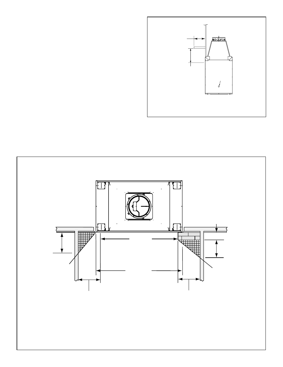
F. Sidewalls/Surrounds
• Adjacent combustible sidewalls must be located
a minimum of 12 in. (305 mm) from the fireplace
opening.
• Combustible or non-combustible mantel legs, surrounds
and stub walls may be constructed per Figure 11.5.
47 in.
[1194 mm]
width of fireplace
42 in.
[1067 mm]
fireplace opening
9 3/4 in.
[248 mm]
12 in.
[305 mm]
12 in.
[305 mm]
11 3/8 in.
[289 mm]
FLUSH
FRONT
4 in.
[102 mm]
BRICK
FRONT
50° angle
39° angle
Gridlines at 1 in. scale
Figure 11.5 Mantel Leg or Wall Projections (acceptable on both sides of opening)
Heat & Glo • HST-48D US-CAN • 4012-040 • Rev F • 11/08