Installation, General safety information, Installation checklist – Hampton Direct H15-LP1 User Manual
Page 7: Clearances to combustibles
Hampton
®
H15-1 Direct Vent Freestanding Gas Stove
7
INSTALLATION
(825mm), a maximum depth of 36" (914mm),
and minimum height of 24" (610mm) from
top of unit to ceiling.
6) We recommend that you plan your instal-
lation on paper using exact measurements
for clearances and fl oor protection before
actually installing this appliance. Have a
qualifi ed building inspector review your plans
before installation.
GENERAL SAFETY
INFORMATION
1) The appliance installation must conform with
local Canadian Electrical Code.
2) The appliance when installed, must be
electrically grounded in accordance with
local codes, or in the absence of local codes
with the current National Electrical Code,
ANSI/NFPA 70 or CSA C22.1 Canadian
Electrical Code.
3) The appliance should be inspected for ship-
ping damage before use and serviced an-
nually by a professional service person.
More frequent cleaning may be required due
to excessive lint from carpeting, bedding
material, etc. It is imperative that control
compartments, and circulating air passage-
ways of the appliance be kept clean and free
from excessive lint from carpeting.
4) See general construction and assembly
instructions. The appliance and vent should
be enclosed when installed in or passing
through a living area, where children may
come in contact with it.
5) This appliance must be connected to the
specifi ed vent and termination cap to the
outside of the building envelope.
Never
vent to another room or inside a building.
Make sure that the vent is fi tted as per the
instructions starting in the "Exterior Vent
Terminal Locations" section.
6) Inspect the venting system annually for
blockage and any signs of deterioration.
7) Venting terminals shall not be recessed into
a wall or siding.
8) Any safety glass removed for servicing must
be replaced prior to operating the appli-
ance.
9) To prevent injury, do not allow anyone who
is unfamiliar with the operation to use the
fi replace.
INSTALLATION
CHECKLIST
1) Locate your gas appliance. Refer to the
following sections:
a. Locating Your Gas Stove
b. Clearances to Combustibles
c. "Venting Introduction" to "Exterior Vent
Terminal Locations" sections.
2) Install Optional Fan. Refer to the "Optional
Fan Installation" section.
3) Set vent restrictor. Refer to the "Vent Restric-
tor Position" section.
4) Install venting: Check all venting require-
ments. See "Venting Introduction" to "Dura-
Vent Vertical Termination" sections.
5) Make gas connections. Refer to the "Gas
Connection" section.
Test the pilot. Must be as per diagram in the
"Pilot Adjustment" section.
If converting to Propane, make changes
prior as instructed in the "Conversion from
Natural Gas to Propane" section.
6) Test Gas Pressure. Refer to the "Gas Pipe
Pressure Testing" section.
7) Install standard and optional features. Refer
to the following sections where applicable:
a. Log Set Installation
b.
Wall
Thermostat
c.
Remote
Control
8) Final check. Refer to the "Final Check" sec-
tion.
Before leaving this unit with the customer, the
installer must ensure that the appliance is fi r-
ing correctly and operation fully explained
to customer.
This includes:
1) Clocking the appliance to ensure the correct
fi ring rate (rate noted on label) after burning
appliance for 15 minutes.
2) If required, adjusting the primary air to ensure
that the fl ame does not carbon. First allow
the unit to burn for 15-20 min. to stabilize.
CAUTION: Any alteration to the product that
causes sooting or carboning that results
in damage is not the responsibility of the
manufacturer.
CLEARANCES TO
COMBUSTIBLES
The clearances listed are MINIMUM distances.
Measure the clearance to both the appliance
and the chimney connector. The farthest
distance is correct if the two clearances do
not coincide.
For example, if the appliance is set as indicated
in one of the fi gures but the connector is too
close, move the stove until the correct clearance
to the connector is obtained.
This appliance may be installed only with the
clearances as shown in the situations pictured.
Do not combine clearances from one type of
installation with another in order to achieve
closer clearances.
This unit can be installed on a solid combustible
surface like a wood fl oor. This unit can also be
installed directly on carpeting or vinyl.
Use the minimum clearances shown in the
diagrams below:
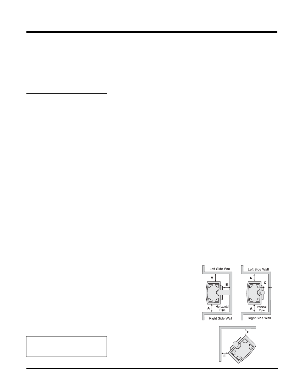
H15-NG1 & H15-LP1 Clearances
A Left Side Wall to Unit*
6" / 150 mm
*B Back Wall to Unit
0" / 0 mm
C Vertical Vent Pipe to Back Wall
2" / 50 mm
E Unit Corner to Wall
2" / 50 mm
Unit Top to Alcove Ceiling 24" / 610 mm
Minimum ceiling height is 24" /610 mm from
top of unit.
*IMPORTANT
It is recommended that unit is moved away from
the wall, if installing the blower option, so the fan
can be easily installed and/or serviced.
Emissions from burning wood or gas could
contain chemicals known to the State of Cali-
fornia to cause cancer, birth defects or other
reproductive harm.