Wiring – Honeywell T6570 User Manual
Page 7
T6570, T8570 SERIES DIGITAL FAN-COIL THERMOSTATS
Table 5. Thermostat Parameter Options
Parameter
ID
Description
°C Scale
°F Scale
Default
Values
Default
Values
Temperature Scale tS
Allows selection of either °C or °F scale Yes
–
No
–
Dead Band
db
Setting deadband (Zero Energy Band) 2
2, 3, 4
4
3, 4, 5
Heat or Cool
Operating Mode
OP
Setting operating mode on single relay,
non-changeover models, to either Heat
or Cool
0
0: cool
1: heat
0
0: cool
1: heat
Unoccupied Cooling
Setpoint
uC
Program unoccupied cooling setpoint
for energy savings.
25
25 to 30
77
77 to 90
Unoccupied Heating
Setpoint
uH
Program unoccupied heating setpoint
for energy savings
18
10 to 18
65
50 to 65
Minimum Cooling
Off Time
CO Setting cooling off-time for short cycle
prevention.
0
0, 3, 4, 5
0
0, 3, 4, 5
Minimum Heating
Off Time
HO Setting heating off-time for short cycle
prevention.
0
0, 3, 4, 5
0
0, 3, 4, 5
Minimum Cooling
Setpoint (Low Limit)
CL
Sets the minimum allowable cooling
setpoint.
10
10 to 30
50
50 to 90
Maximum Heating
Setpoint (High Limit)
HL
Sets the maximum allowable heating
setpoint.
30
10 to 30
90
50 to 90
Energy Savings
Configuration
ES
Activate energy savings mode by a
choice of either contact closure or
contact opening.
1
1: normally open
0: normally closed
1
1: normally open
0: normally closed
Display of Room
Temperature
rt
Allows installer to restrict temperature
display to set point only. With this
parameter, the unit will only display the
set point temperature. Useful where
setpoint limits (HL and CL) will affect
control performance and Room
Temperature display will disagree with
user setpoint.
1
1: room temp.
0: setpoint only
1
1: room temp.
0: setpoint only
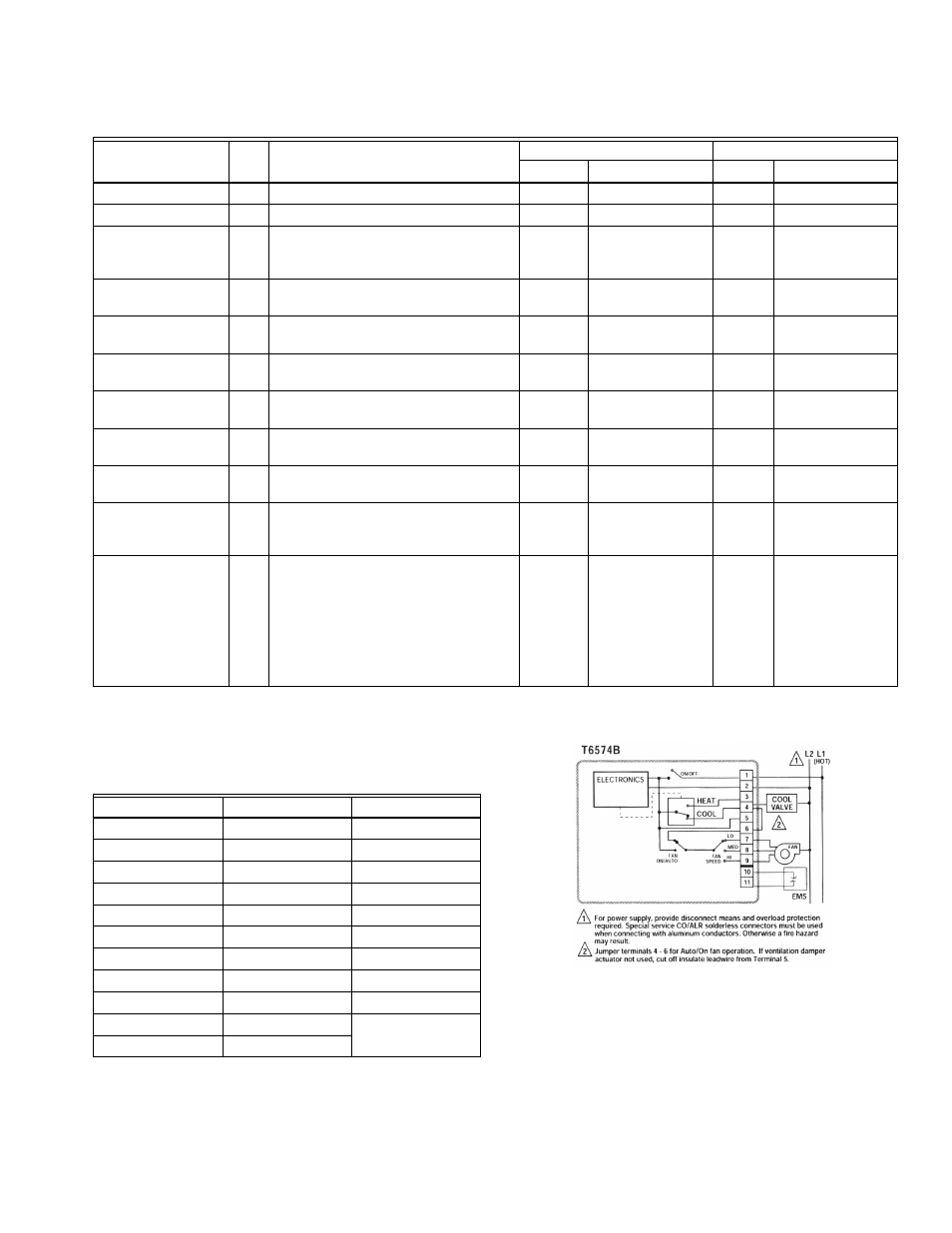
WIRING
Table 6. Leadwire Color Code (if fitted)
Terminal
Color
Use
1
Black (BK)
L1 (Hot)
2
White (WH)
L2 (N)
3
Orange (OR)
Heat
4
Yellow (YL)
Cool
5
Gray (GY)
Damper
6
Violet (VI)
Fan Common
7
Red (RD)
Fan Low
8
Blue (BU)
Fan Medium
9
Brown (BN)
Fan High
10
–
Energy Mgt.
System
11
–
Fig. 6. Wiring 2-pipe cool-only thermostat with fan On/Auto
switch.
7
95C-10897–6