Caution, Wiring remote sensor – Honeywell T6570 User Manual
Page 10
T6570, T8570 SERIES DIGITAL FAN-COIL THERMOSTATS
Fig. 19. Wiring 4-pipe 24V auto heat/cool changeover with
continuous fan.
Fig. 20. Wiring 4-pipe 24V auto heat/cool changeover
thermostat with fan On/Auto switch.
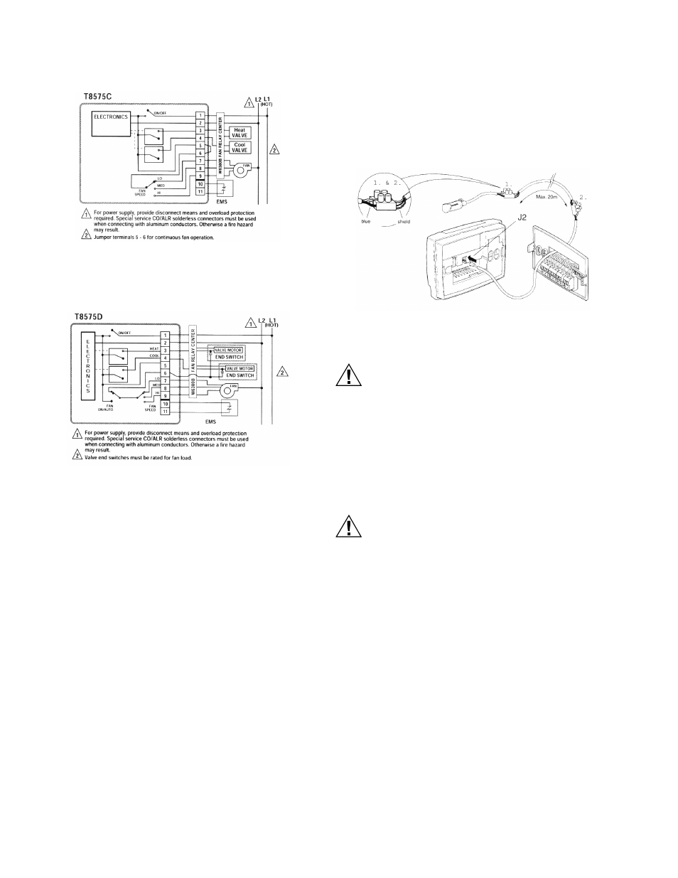
Wiring Remote Sensor
The T8109 is a optional remote sensor that can be used as an
alternative to the internal sensor of the T8575D. The T8109
remote sensor plugs into the J2 header in the back of the
thermostat. On power-up the T8575D will look for a T8109 and
if there is one connected it will use this control. If it does not
find a T8109 connected it will use the internal sensor. To
change the sensor source, turn off the thermostat power and
disconnect the current sensor source. Then connect the new
sensor source and re-power the thermostat. On powerup the
T8575D will find the new sensor source and use this for
control. To extend the sensor cable, up to a maximum of 70
feet (20m), use only shielded cable. For example, Beldfoil® 18
AWG cable is a suitable cable. The sensor connections are
polarity sensitive, so be sure to connect the shielded wire to
the sensor blue wire, as shown in Fig. 21 below.
Fig. 21. Wiring optional remote sensor for the T8575D
model.
CAUTION
Equipment Damage Hazard.
Operation at low temperatures can cause fan coil
damage.
This thermostat is not a safety device. Do not use it
where the space temperature is outside of the device
operating range.
A display of SF indicates a space temperature outside
of the thermostat operating range (5°C to 45°C).
With SF displayed, the thermostat ceases to
operate.
CAUTION
Equipment Damage Hazard.
Improper operation can cause compressor
damage.
Do not operate cooling if outdoor temperature is below
50ºF (10°C). Refer to manufacturer recommendations.
To avoid compressor damage, allow the compressor to
remain off for five minutes before restarting.
95C-10897–6
10