2 wiring port s1 for rs-485-two-wire, Figure 11 port s1 jumpers and dip switches, Wiring port s1 for rs-485—two-wire – Emerson SiteLink-12E User Manual
Page 15
Communication and Control Wiring
11
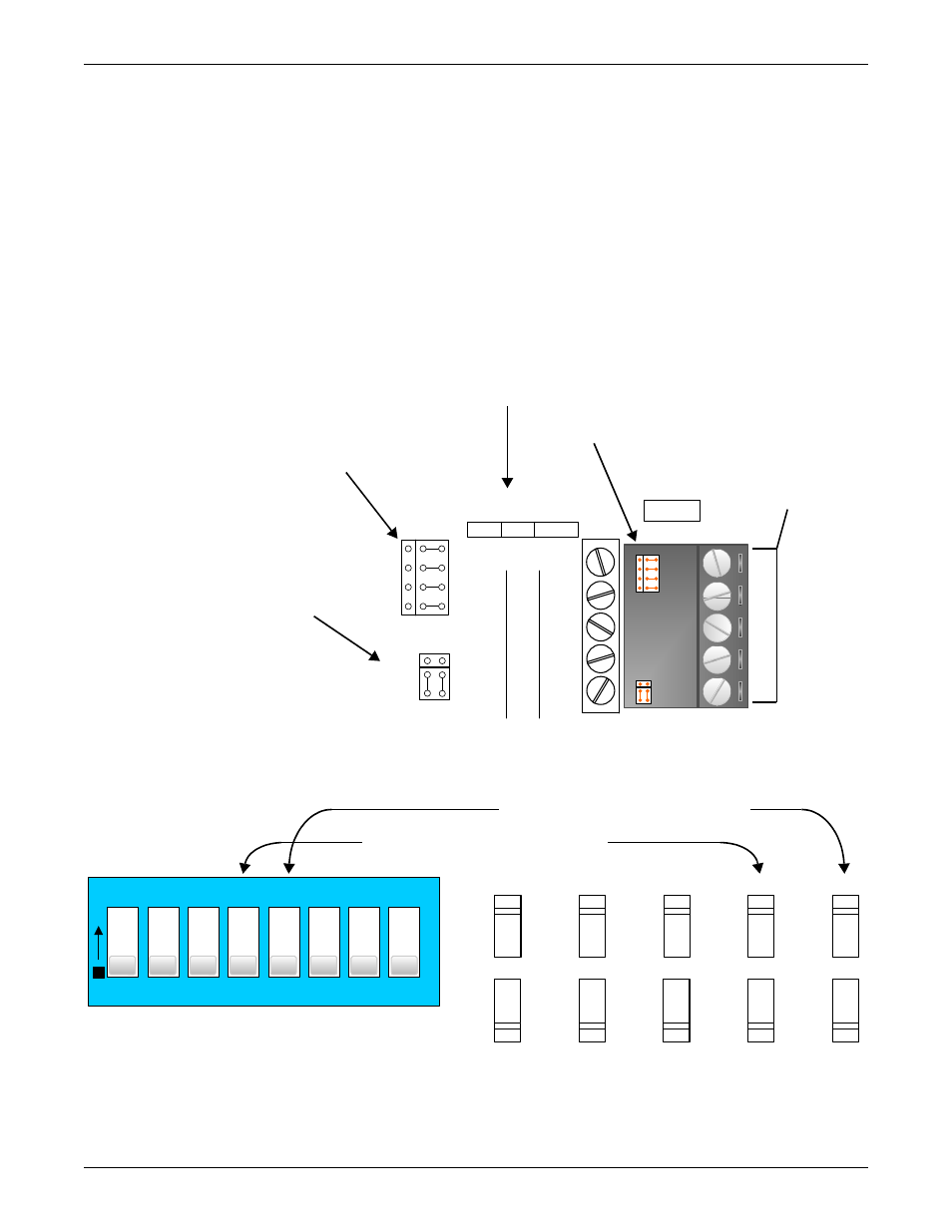
4.4.2 Wiring Port S1 for RS-485—Two-Wire
For connecting the Liebert SiteLink-E Port S1 to a BMS that uses two-wire RS-485:
• Liebert recommends using shielded, 18-24AWG twisted pair wiring.
• The distance from the Liebert SiteLink-E module to the first RS-485 device depends on the com-
munications baud rate. This distance seldom should exceed 3,000 ft. (914.4m) at 9600 baud.
1. Be sure that power to the Liebert SiteLink-E is Off before beginning to connect wiring.
2. Check the communication wiring for shorts and grounds.
3. Wire the Liebert SiteLink-E to the third-party device, using the labels near Port S1 as a guide
(see Figure 11 for details).
4. Set the RS-232 or RS-485 jumper to RS-485.
5. Set the MS/TP on S1 DIP switch to Enable (On).
6. Set the PTP on S1 DIP switch to Disable (Off).
Figure 11 Port S1 jumpers and DIP switches
n/c
n/c
Net-
Net+
Port S1
2 wire 4 wire EIA-232
Signal Ground
DCD
DTR
Rx
Tx
Rx -
Rx +
Tx -
Tx +
BT485
EIA
-4
8
5
EIA
-2
3
2
485-4w
485-2w
1
2
3
4
5
6
7
8
O
N
Disable
Disable
+0
Default
Off
1
2
3
4
5
Enable
Assigned
Enable
+100
On
Sw
Enhanced Access
On Rnet
IP Addr
Address
MSTP
On S1
PTP
On S1
Connect Communication Wiring
to Terminals According to Labels
Behind Ports
Terminals
Set Jumpers for RS-232
and RS-485 According
to Labels
Jumpers for
RS-232 and
RS-485
Set Jumpers for Using
2-Wire or 4-Wire 485
Cables According
to Labels
Port S1
(at bottom right corner
of module
DIP switch Labels
(in upper middle of module)
DIP switches
(at top of module, near battery
Set DIP switch 5 to Disable for MS/TP
Set DIP switch 5 to Enable for PTP
Set DIP switch 4 to Enable for MS/TP
Set DIP switch 4 to Disable for PTP