2 rs-485 and arc156 wiring considerations, 3 wiring for bacnet/arc156 network, Figure 9 bacnet/arc156 network port – Emerson SiteLink-12E User Manual
Page 13: Rs-485 and arc156 wiring considerations, Wiring for bacnet/arc156 network, Figure 9, Bacnet/arc156 network port, Bacnet
Communication and Control Wiring
9
4.2
RS-485 and ARC156 Wiring Considerations
An RS-485 network is intended to be configured as a linear bus with daisy-chained connections (star
topologies are not recommended). Termination in RS-485 and ARC156 setups is usually applied to
both ends of the network (see 4.4.1 - Wiring Port S1 for RS-485 Network—Four-Wire).
Repeaters often are required when connecting 32 or more RS-485 or ARC156 devices or when using
ARC156 cable segments longer than 2000 feet. Refer to the BMS documentation for information on
when to use repeaters.
To reduce communication and data errors, terminate each end of the network with a resistor whose
value equals the network's characteristic impedance. Some third-party manufacturers provide a
built-in resistor that you enable or disable with a jumper. Make sure that only devices at the end of a
network have termination enabled.
EXAMPLE: If the network’s characteristic impedance is 120 Ohms, terminate the network by
placing a 120 Ohm resistor across the Net+ and Net- connectors of the Liebert SiteLink-E and a
120 Ohm resistor across the + and - connectors of the furthest third-party device.
Bias must be applied to each RS-485 network segment. To add bias to a network segment, put the
bias jumper in place on the DIAG485 that is in the middle of the segment. You can use additional
DIAG485s with the bias jumper removed to monitor network communication, but only one
DIAG485 may have the bias jumper in place.
4.3
Wiring for BACnet/ARC156 Network
Network Liebert SiteLink-E modules to other Liebert Site Scan modules using the ARCnet port. Set
the baud rate to 156 Kbps for all modules connected to the ARCnet156 network.
1. Be sure the module’s power is Off before beginning to connect wiring for the ARCnet port.
2. Check the network communication wiring for shorts and grounds.
3. Locate the BACnet terminal location in the upper left corner of the Liebert SiteLink-E module
(see Figure 1).
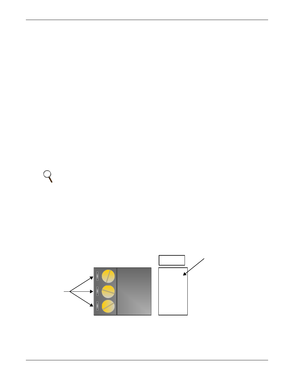
4. Connect the communication wiring to the control module’s screw terminals labeled Net +, Net -
and Shield using the labels near the ARCnet port as a guide. For details, see Figure 9..
Figure 9
BACnet/ARC156 Network port
NOTE
Use the same polarity throughout the network segment.
BT485
BACnet
®
Over ARCNET156 KBaud
Net +
Net -
Shield
ARCnet
Port
Connect Communication
Wiring to Terminals Using
Label Behind Port as
Guide
Wiring
Terminals