Rear panel features and operation, Operation, cont’d, Xtra series • operation – Extron electronic XPA 200170V User Manual
Page 14: 4 xtra series • operation
XTRA Series • Operation
Operation, cont’d
3-4
XTRA Series • Operation
3-5
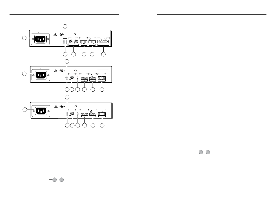
Rear Panel Features and Operation
100-240V 0.5A, 50-60Hz
CLASS 2 WIRING
1
2
LISTED 17TT
AUDIO/VIDEO
APPARATUS
XPA 1002
C
US
LEVEL
1
1
2
1
2
LIMITER/
PROTECT
SIGNAL
2
INPUTS
OUTPUT
REMOTE
0
0
10V
50 mA
VOL/MUTE
STANDBY
XPA 1002
Rear Panel
1
2a
3a
4
5a
6
7a
CLASS 2 WIRING
STANDBY
L
(MONO)
R
LISTED 17TT
AUDIO/VIDEO
APPARATUS
C
US
XPA 2001-70V
OUTPUT
70 V
LEVEL
HFP
INPUTS
REMOTE
0
LIMITER/
PROTECT
SIGNAL
100-240V 0.5A, 50-60Hz
80 Hz
OFF
VOL/MUTE
10V
50 mA
XPA 2001-70V
Rear Panel
1
3b 4
6
2b
7b
5b
8
CLASS 2 WIRING
STANDBY
L
(MONO)
R
LISTED 17TT
AUDIO/VIDEO
APPARATUS
C
US
XPA 2001-100V
OUTPUT
100 V
LEVEL
HFP
INPUTS
REMOTE
0
LIMITER/
PROTECT
SIGNAL
100-240V 0.5A, 50-60Hz
80 Hz
OFF
VOL/MUTE
10V
50 mA
XPA 2001-100V
Rear Panel
1
3b 4
6
2b
7b
5b
8
a
AC power connector — Connect a standard IEC AC power cord
here for power input (100 VAC to 240 VAC, 50/60 Hz) to the
internal, autoswitching power supply. This connector may be
replaced by the PS 123 Flexible Conduit Adapter Kit (part
#70-228-02
) as described in "Flexible conduit adapter kit
installation" in chapter 2.
Ç
Limiter/Protect indicator LEDs (channels 1 and 2) — These
LEDs (representing output channels 1 and 2) light red under
four circumstances:
1
2
LIMITER/
PROTECT
• When the output wiring is shorted together
• When audio clipping occurs, the corresponding channel’s
LED blinks once per clip occurrence.
• When the amplifier overheats, both LEDs are lit. The LEDs
are not lit after the amplifier cools down and recovers from
the overheated condition.
• When DC output is detected, the amplifier is malfunctioning
and the LED for the corresponding channel is lit. When a
malfunction occurs, power down the amplifier and power it
back up. If the LED still remains lit, the amplifier requires
servicing.
See step
Ñ
of "Front Panel Features and Operation" in this
chapter.
É
Limiter/Protect indicator LED — This LED (representing the
output channel) lights red under four circumstances:
• When the output wiring is shorted together
• When audio clipping occurs, the LED blinks once per clip
occurrence.
• When the amplifier overheats, the LED is lit. The LED is
not lit after the amplifier cools down and recovers from the
overheated condition.
• When DC output is detected, the amplifier is malfunctioning
and the LED is lit. When a malfunction occurs, power down
the amplifier and power it back up. If the LED still remains
lit, the amplifier requires servicing.
See step
Ö
of "Front Panel Features and Operation" in this
chapter.
Ñ
Signal indicator LEDs (channels 1 and 2) — These LEDs
(representing input channels 1 and 2) light green only when an
input signal is detected on the corresponding channel.
1
2
SIGNAL
See step
Ü
of "Front Panel Features and Operation" in this
chapter.
Ö
Signal indicator LED — This LED (representing the input
channel) lights green only when an input signal is detected.
d
Level adjustment (channels 1 and 2) — Use a Tweeker or
small screwdriver to adjust the audio input level for the
corresponding channel. The analog potentiometers control the
level from -= (full attenuation) to 0 dB.