Installation, cont’d – Extron electronic XPA 200170V User Manual
Page 11
XTRA Series • Installation
Installation, cont’d
2-8
XTRA Series • Installation
2-9
100-240V 1.3A
, 50-60H
z
VO
L/MUTE
10V
STANDBY
CLASS 2
WIRING
1
2
LISTED 17TT
AUDIO/VIDEO
APP
ARA
TUS
CLASS 2
WIRING
XP
A 1002
C
US
LEVEL
1
1
2
1
2
LIMITER/
PR
OT
ECT
SIGNAL
2
INPUTS
OUTPUT
REMO
TE
0
0
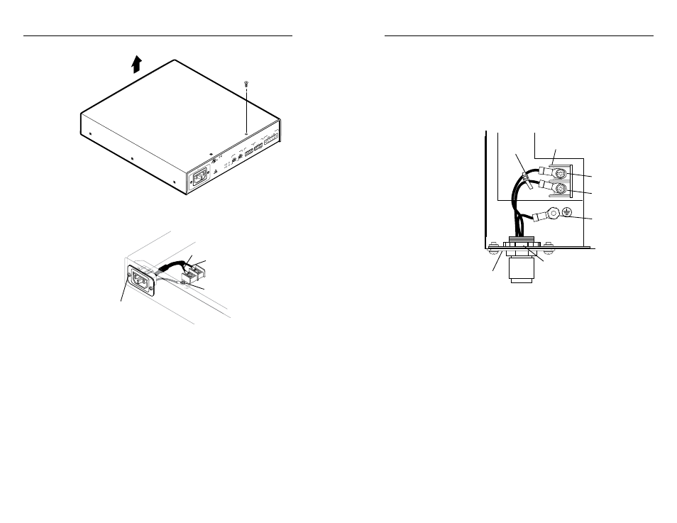
Remove (8)
screws
Lift Cover Straight Up
3
.
Remove the 2 screws holding the hot (line) and neutral
wires from the terminal block on the PCB.
100-240V 1.3A
50-60Hz
Remove screws
(both sides) to release
IEC connector plate.
Remove nut
Blue Wire
Brown Wire
L
N
4
.
Remove the ground wire nut from the grounding stud on
the bottom of the enclosure, as shown above.
5
.
Remove the 2 screws from the IEC plate, and remove the
IEC connector plate and the attached wires through the
rear panel of the XPA, as shown above.
6
.
Thread the 18-gauge power wires through the length of the
electrical conduit tube.
7
.
Install the EMT adapter plate with conduit attached into
the opening from which the IEC connector was removed.
in step 5.
8
.
Slide the conduit nut over the bundle of wires exiting the
conduit and onto the conduit itself. Hand tighten the
conduit nut to the conduit.
9
.
Attach the EMT adapter plate assembly to the XPA using
the 2 screws that were removed in step 5.
10
. Connect the black hot (line) and white neutral wires to
the terminal block on the PCB using the 2 screws that
were removed in step . Use the included zip tie wrap to
secure the two wires together close to the terminals. See
the following illustration.
W
Ensure that you observe correct wire polarity. The
following illustration shows the location of the hot
(L) and neutral (N) terminals.
LINE
NEUTRAL
L
N
Conduit Nut
EMT Adapter Plate
Terminal Block
Zip-Tie
Ground
Wire Nut
Hot
Terminal (Black)
Neutral
Terminal (White)
11
. Connect the ground wire, as shown above, to the
grounding stud on the bottom of the enclosure using the
nut that was removed in step 4.
12
. Replace the cover of the XPA by attaching the 8 screws that
were removed in step 2.