Terminal block connections, Vivotek - built with reliability, Com no – Vivotek ND9542P 32-Channel 4K UHD NVR (No HDD) User Manual
Page 24: 24 - user's manual
VIVOTEK - Built with Reliability
24 - User's Manual
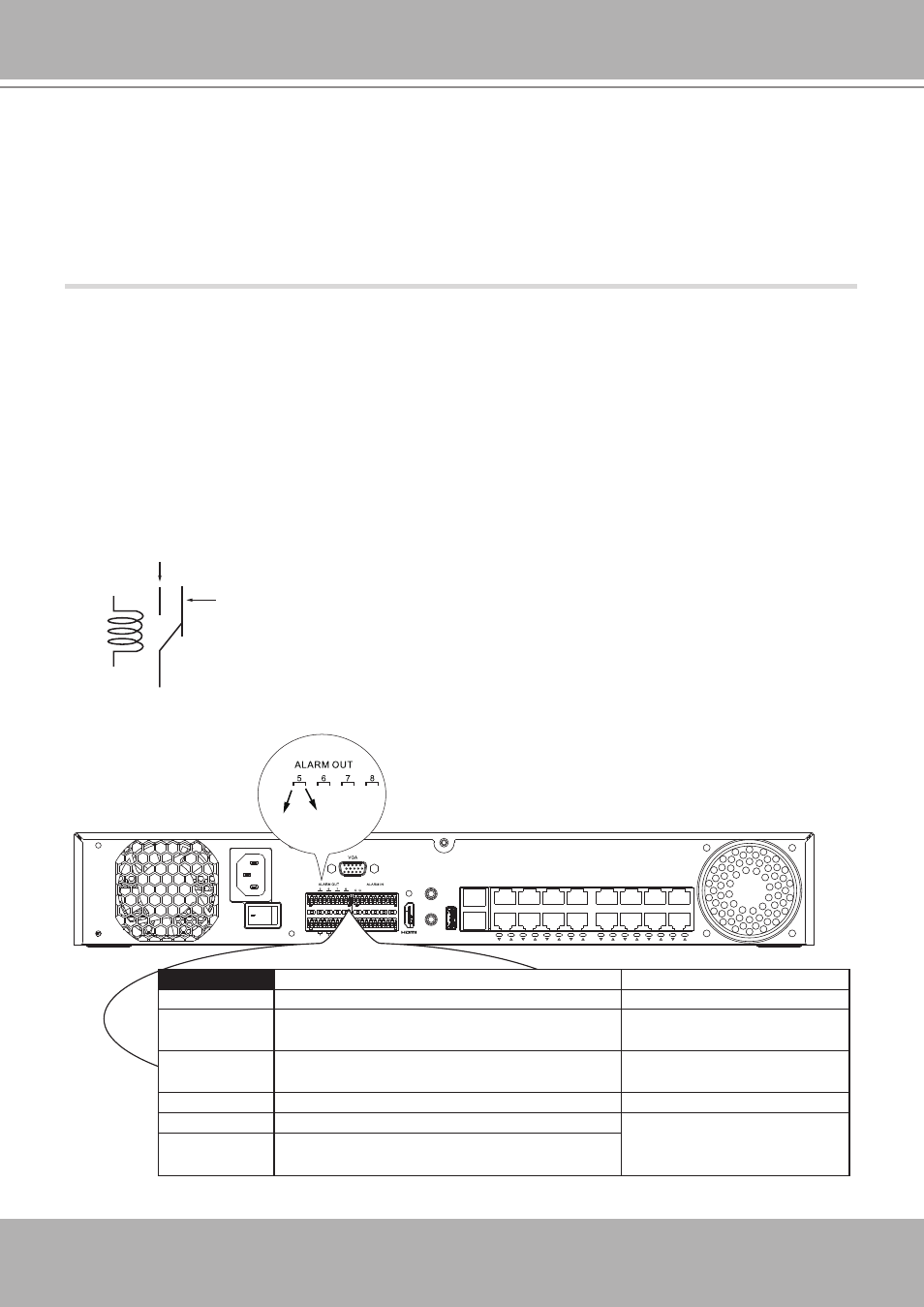
Terminal Block Connections
The terminal block pinouts is shown as follows:
The relay pins default status is set to Normally Open. Connect your relay or external devices’
signal wires to the system, the system will automatically detect the current signal status. You
can then trigger the external devices using the DI/DO panel on the live view.
You can also configure the system alarm setting for the system to automatically trigger a relay
pin on the occurrence of system events. See Alarm settings on page 129.
ssss
8
7
6
5
4
3
2
1
USB 3.0
AUDIO OUT
AC IN
100~240V
AUDIO IN
+
-
RS485
NET 1
1
2
NET 2
4
6
8
10
12
14
16
3
5
7
9
11
13
15
16
15
14
13
12
11
10
9
COM NO
Normally Open
pin
Common pin
Normally Closed
pin
Coil
Pin
Description
NOTE
DI no. 1~8
Open-short-to-GND
G
Pins # 1~4 share a common ground.
Pins # 5~8 share a common ground.
NO
Normally open. Use the DO trigger buttons on the
live view window to trigger the digital output.
COM
Common pin
RS485+
RS485 Data+
A 120Ω terminator is enabled on
the bus. The terminator cannot
be disabled.
RS485-
RS485 Data-
The GND are common ground for the DIs.
2-6.
Limitations
:
•
When you are exporting video to the disk drives in an external storage, you cannot
select the other disk drives to create a new volume.
•
If the disk drives or volumes in the external storage is smaller than 1TB, you
cannot configure them as volumes for the NVR.
•
The connection interface to external storage must comply with the USB 3.0
specifications.