Figure 18b: low line voltage thermostat wiring, Figure 20: ener-radiant xl burner internal wiring – Enerco ERXL-125S User Manual
Page 20
20
Enerco | enerRadiant® XL Series Heater
Operating Instructions and Owner’s Manual
SECTION 6
Wiring
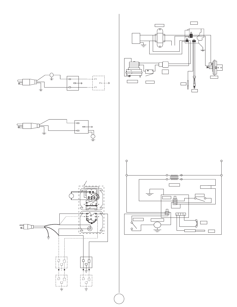
Heaters are normally controlled by thermostats. Line voltage
thermostats are wired directly (see Figure 18a), the recommended
24V thermostats use a relay (see Figure 18b). Heaters must be
grounded in accordance with the National Electric Code ANSI/NFPA -
70 - latest version. Heaters may also be controlled with a manual line
voltage switch or timer switch in place of the thermostat.
FIGURE 18a: Line Voltage Thermostat Wiring
T
H
N
120v – 60 Hz
White
White
Green
Green
Supply Circuit
120v – 60 Hz
Supply Circuit
Burners
(Maximum – 2 per Thermostat)
Burners
(Maximum – 1 per Thermostat)
Black
Black
H
N
T
FIGURE 18b: Low Line Voltage Thermostat Wiring
T
H
N
120v – 60 Hz
White
White
Green
Green
Supply Circuit
120v – 60 Hz
Supply Circuit
Burners
(Maximum – 2 per Thermostat)
Burners
(Maximum – 1 per Thermostat)
Black
Black
H
N
T
FIGURE 20: Ener-Radiant XL Burner Internal Wiring
B
C
W
Black
Black
White
White
Burner 3
120V – 60Hz
Supply Circuit
Burner 1
Burner 2
Burner 4
White
N
H
N
H
Red
Red/Yellow*
Purple*
Black
Green
Whit
e
G
Y
3
6
5
4
2
T
Transformer Relay
FIGURE 19: Wiring of Low Voltage Thermostat and Relay
When using 1-2 burners, use SPDT Transformer Relay / Stk. # 00172
When using 3-4 burners, use DPDT Transformer Relay / Stk. # 00183
Wires marked with an asterisk (*) are for use only with DPDT
Transformer Relay.
•
If any of the original wire as supplied with the
appliance must be replaced, it must be replace with
wiring material having a temperature rating of at least
105°C and 600 volts.
•
Each burner must be electrically grounded in
accordance with the National Electric Code ANSI/NFPA
- 70 - latest version.
FIGURE 21: Ener-Radiant XL Burner Internal Wiring Ladder
Diagram
VAC
120
120V
24V
Black
Black
Purple
Yello
w
Yello
w
Black
Black
Black
Green
Green
Orange
Transformer
White
White
White
THERMOSTAT
White
Blue
Gas Valve
Air Switch
Ignitor
Sensor
Motor / Blower
Door Switch
Terminal
Bushing
120V
L2
(NEUTRAL)
White
White
White
White
White
White
Gray
Orange
Transfomer
Thermostat
Air Switch
Gas Valve
Door Switch
Motor / Blower
Ignitor
Sensor
Blue
Yellow
Yellow
Purple
Black
Black
Black
Black
L2 (HOT)
24V
Low Voltage Thermostat
Stk. #10368