Location of controls and indicators – Emerson Radio SB251 User Manual
Page 9
8
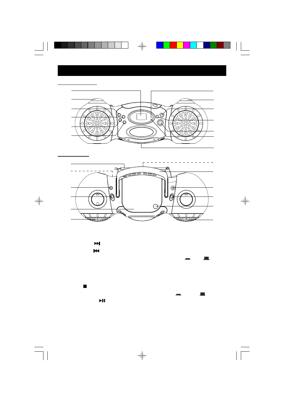
LOCATION OF CONTROLS AND INDICATORS
1.) INTRO Button.
2.) PROGRAM Button.
3.) FWD. SKIP
Button.
4.) REV. SKIP
Button.
5.) VOLUME Control.
6.) LCD Display.
7.) POWER “On” Indicator.
8.) TUNING Control.
9.) STOP Button.
10.) REPEAT Button.
11.) PLAY/PAUSE
Button.
12.) FM ST Indicator.
13.) Battery Compartment.
(Bottom Cabinet)
14.) Speakers.
15.) CD Door.
16.) FUNCTION Selector Switch.
(POWER OFF/CD/RADIO)
17.) BASS BOOST ON
/OFF
Button.
18.) AC Cord Socket. (Back Cabinet)
19.) Telescopic Antenna.
20.) PHONES Jack. (Back Cabinet)
21.) Carrying Handle.
22.) FM MODE ST
/MONO
Button.
23.) BAND (FM/AM) Selector Switch.
24.) CD Door OPEN/CLOSE Position.
14
15
16
17
18
19
20
21
22
23
24
14
1
2
3
4
5
7
8
9
10
11
6
12
13
FRONT PANEL
TOP PANEL
SB250_251_ib071703.p65
17/7/2003, 14:27
8
This manual is related to the following products: