3 hardware installation, Fixed camera by screws – PLANET ICA-HM240 User Manual
Page 12
11
2.3 Hardware
Installation
2.3.1 Camera
Mounting
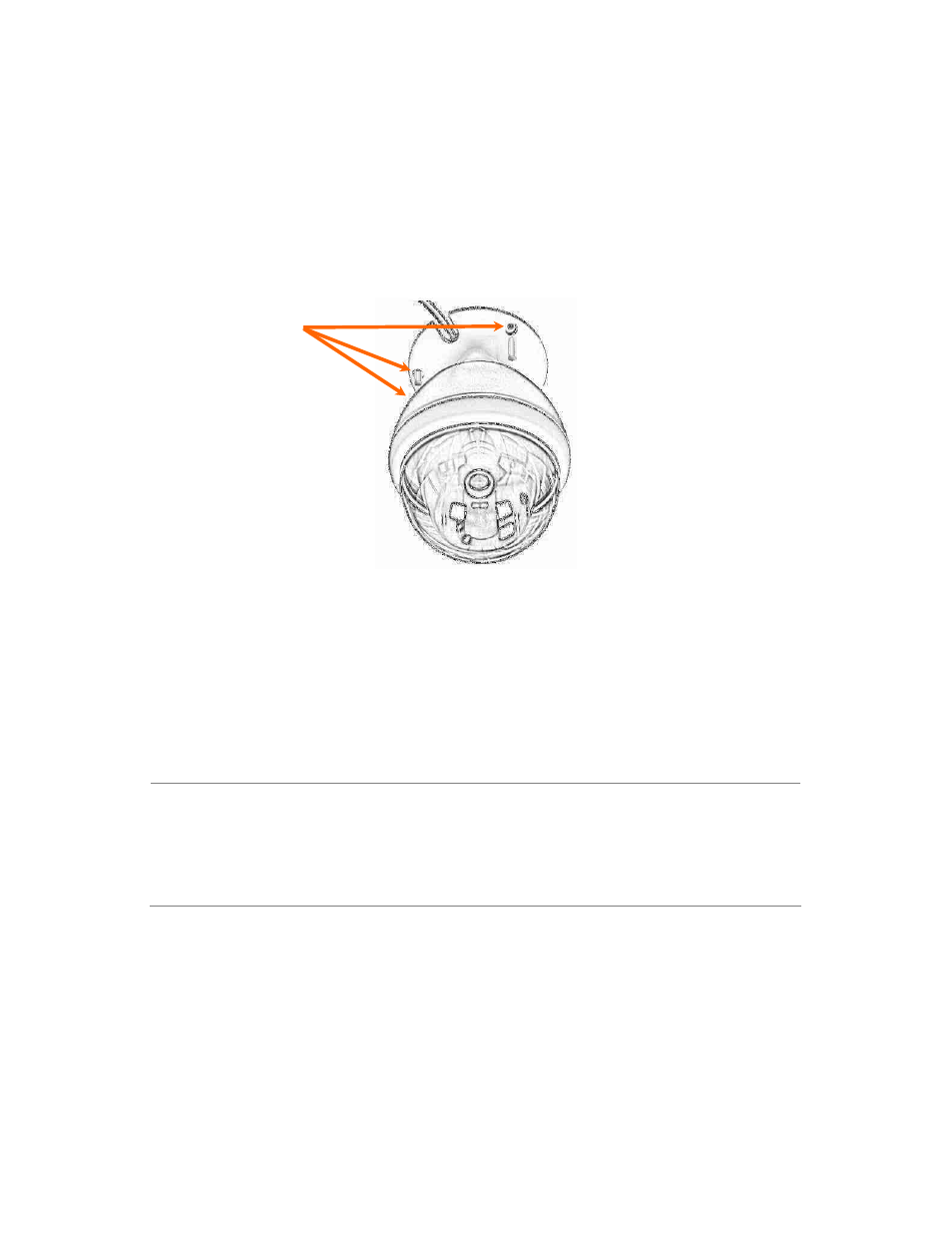
Step 1.
Fix the IP camera to ceiling with the three supplied supplied screws.
Step 2.
Connect the LAN cable to a switch or hub. When this switch/hub is a PoE device, you
can ignore the next step.
Step 3.
Connect (DC) Power Jack to the with the bundle power adapter power source.
Step 4.
Check the status LED. When LAN port is connected, the LED will be green. The LED is
defined to identify LAN connection status
NOTE:
1. Only use the power adapter supplied with IP camera Otherwise, the product
may be damaged.
2. The power adapter is unnecessary when IP camera is connected to a
IEEE802.3af PoE switch. Otherwise, the product may be damaged when IP
camera is connected to a PoE switch and power adapter simultaneously.
Fixed Camera
by Screws
- FNSW-1601 (2 pages)
- FNSW-1601 (2 pages)
- FGSW-1816HPS (2 pages)
- FGSW-1816HPS (110 pages)
- FGSW-1816HPS (105 pages)
- WGSD-10020HP (16 pages)
- GS-5220-16S8CR (432 pages)
- FGSD-1022P (226 pages)
- FGSD-1022P (12 pages)
- FGSD-910P (28 pages)
- FGSW-1602RS (30 pages)
- FGSW-2402S (39 pages)
- FGSW-2620PVS (50 pages)
- FGSW-2624SF (2 pages)
- FGSW-2620VM (213 pages)
- FGSW-2620VM (2 pages)
- FGSW-2624SF (2 pages)
- FGSW-2620VM (96 pages)
- FGSW-2620 (2 pages)
- FGSW-2620CS (2 pages)
- FGSW-2620CS (81 pages)
- FGSW-2620CS (2 pages)
- FGSW-2620CS (80 pages)
- FGSW-2840 (2 pages)
- FGSW-4840S (263 pages)
- FGSW-4840S (2 pages)
- FGSW-4840S (38 pages)
- FNSW-1600P (20 pages)
- FNSW-1600S (33 pages)
- FNSW-2400PS (2 pages)
- FNSW-2400PS (70 pages)
- FNSW-1602S (43 pages)
- FNSW-2402S (39 pages)
- FNSW-4800 (2 pages)
- FNSW-2401CS (38 pages)
- FSD-1604 (12 pages)
- FSD-2405 (18 pages)
- FSD-1606 (2 pages)
- FSD-803 (2 pages)
- FSD-803 (2 pages)
- FSD-504HP (2 pages)
- FSD-805ST (20 pages)
- FSD-804P (21 pages)
- FSD-808P (20 pages)
- FSD-808P (22 pages)