Installation instructions, 27 type 2, Lrp injector – PLANET LRP-101C-KIT User Manual
Page 27: Lrp extender, Step 1, Step 2, Step 3, Step 4
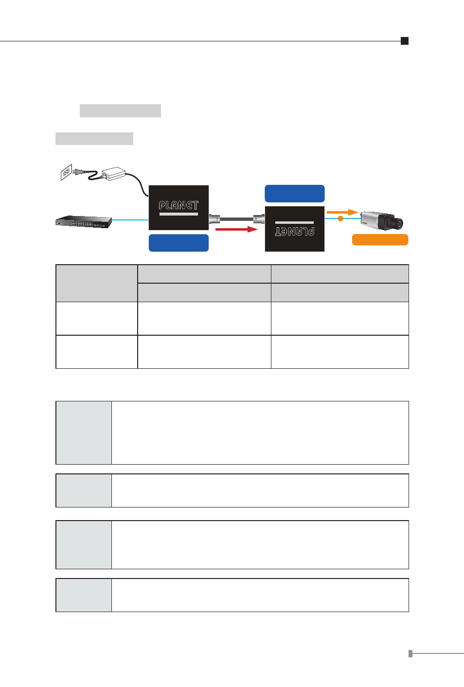
27
Type 2
–
One LRP-101CH with 48~56V power adapter and one
LRP-101CE with PoE power output
The
LRP Injector
is powered via the external power adapter. The
IEEE 802.3at/af compliant PoE PD will automatically be powered by the
LRP Extender
via UTP.
Power over Coaxial
802.3af/802.3at
PoE
PoE IP Camera
Ethernet Switch
LRP-101CH
Long Reach PoE Injector
LRP-101CE
Long Reach PoE Extender
110-240V AC
AC-to-DC Adapter
60W/48~56V DC IN
PoE
CAT5e/6
CAT5e/6
Long Reach Power over Ethernet
Long Reach Power over Ethernet
Functions
LRP Injector
LRP Extender
LRP-101CH
LRP-101CE
Power Input
Power adapter with
48~56V DC in
BNC with DC power over
coaxial input
Power
Output
BNC with DC power over
coaxial output
RJ45 with 802.3at/af
PoE output
Installation Instructions
Step 1
Connect the LRP Injector (LRP-101CH) and LRP
Extender (LRP-101CE) to ends of BNC terminated
coaxial cable.
Stick the “Warning Sticker” on the coaxial cable.
Step 2
Connect Cat5/6 UTP cable to LRP-101CH and non-PoE
switch or workstation.
Step 3
Connect 48~56V DC power adapter to LRP-101CH power
socket, then the PWR LED of LRP-101CH and LRP-101CE
should lit up immediately.
Step 4
Connect Cat5/6 UTP cable to LRP-101CE and IEEE
802.3at/af complied PoE IP camera or PoE Wireless AP.