PLANET GSD-504 User Manual
Installing the switch, Package contents, Switch top panel
- 1 -
- 2 -
- 3 -
- 4 -
- 5 -
- 6 -
- 7 -
- 8 -
6. Installing the Switch
This part describes how to install your Gigabit Ethernet
Switch and make connections to it. Please read the
following topics and perform the procedures in the order
being presented.
Note
This Switch does not need software configu�
not need software configu�
ration.
Desktop Installation
To install the Switch on desktop, simply follow the next
steps:
Step 1: Place the Switch on desktop near an AC power
source.
Step 2: Keep enough ventilation space between the
Switch and the surrounding objects.
Note
When choosing a location, please keep in
mind the environmental restrictions dis�
cussed in Chapter 7. Product Specifications.
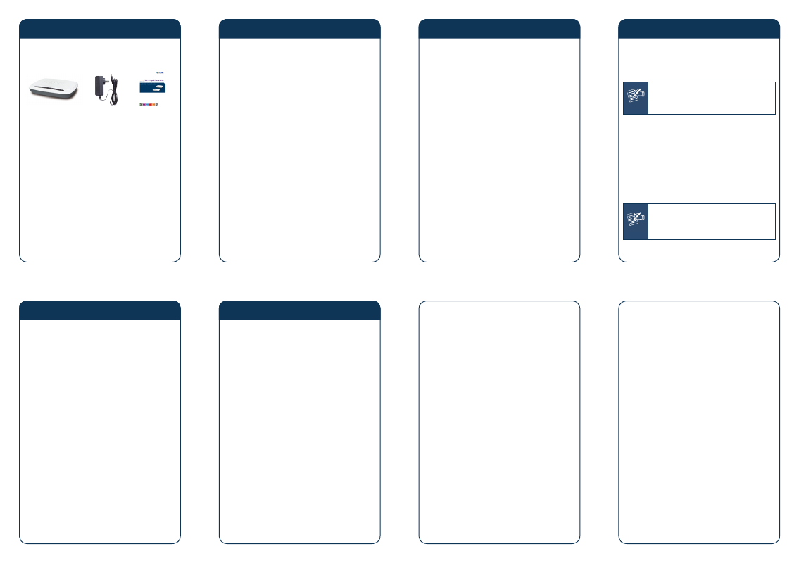
1. Package Contents
Check the contents of your package for following parts:
Gigabit Ethernet
Switch x 1
DC 5V
1A Power
Adapter x 1
User’s
Manual x 1
If any of these are missing or damaged, please contact
your dealer immediately, if possible, retain the carton
including the original packing material, and use them
against to repack the product in case there is a need to
return it to us for repair.
3. Switch Top Panel
Figure 3�1 & 3�2 shows a Top panel of GSD�504 /
GSD�804.
Figure 3-1: GSD-504 Top panel
Figure 3-2: GSD-804 Top panel
5. Switch Rear Panel
Figure 5�1 & 5�2 shows a rear panel of GSD�504 /
GSD�804.
1
3
5
4
2
Figure 5-1: GSD-504 rear panel
1
3
5
7
4
6
8
2
Figure 5-2: GSD-804 rear panel
2. Product Features
Comply with IEEE 802.3, 10Base�T, IEEE 802.3u
100Base�TX, IEEE 802.3ab 1000Base�T
Power Saving ability for Green networking
5/8�Port 10/100/1000Mbps Gigabit Ethernet ports
Features Store�and�Forward mode with wire�speed
filtering and forwarding rates
Hardware based 10/100Mbps, Half / Full Duplex and
1000Mbps Full Duplex mode, Flow Control and Auto�
negotiation
IEEE 802.3x Flow Control for Full Duplex operation
and Back pressure for Half Duplex operation
Integrated address look�up engine, support 8K
absolute MAC addresses
Automatic Address Learning and Address Aging
9K Jumbo packet size
Supports Auto MDI/MDI�X function
Support CSMA/CD protocol
FCC, CE class B compliant
4. LED Indicators
Figure 4�1 & 4�2 shows a LED panel of GSD�504 /
GSD�804.
Figure 4-1: GSD-504 LED panel
Figure 4-2: GSD-804 LED panel
LED
Color
Function
PWR
Green
Light
Indicate that the Switch is
Powered ON.
OFF
Indicate that the Switch is
Powered OFF.
Link/ACT Green
Light
Indicates the link
through that port is
successfully established at
10/100/1000Mbps.
Blink
Indicates the Switch is
actively sending or receiving
data over that port.
Step 3: Connect your Switch to network devices.
A. Connect one end of a standard network
cable to the 10/100/1000 RJ�45 ports on
the rear panel of the Switch.
B. Connect the other end of the cable to the
network devices such as printer servers,
workstations or routers…etc.
Step 4: Supply power to the Switch.
A. Connect one end of the power cable to the
Switch.
B. Connect the 5V DC power adapter to a
standard wall outlet.
When the Switch receives power, the Power LED should
remain solid Green.
PC/Laptop
xDSL/Cable Router
Internet
Power Adapter
RJ-45
RJ-45
Power
001101010
1
3
5
7
4
6
8
2
Power
Notice
1. The device is a power�required device, it
means, it will not work till it is powered.
If your networks should active all the
time, please consider using UPS (Uninter�
rupted Power Supply) for your device. It
will prevent you from network data loss
or network downtime.
2. In some area, installing a surge suppres�
sion device may also help to protect your
Switch from being damaged by unregu�
lated surge or current to the Switch or
the power adapter.