Appendix a networking connection, A.1 data out poe switch rj-45 port pin assignments – PLANET FSD-808P User Manual
Page 19
19
Appendix A Networking Connection
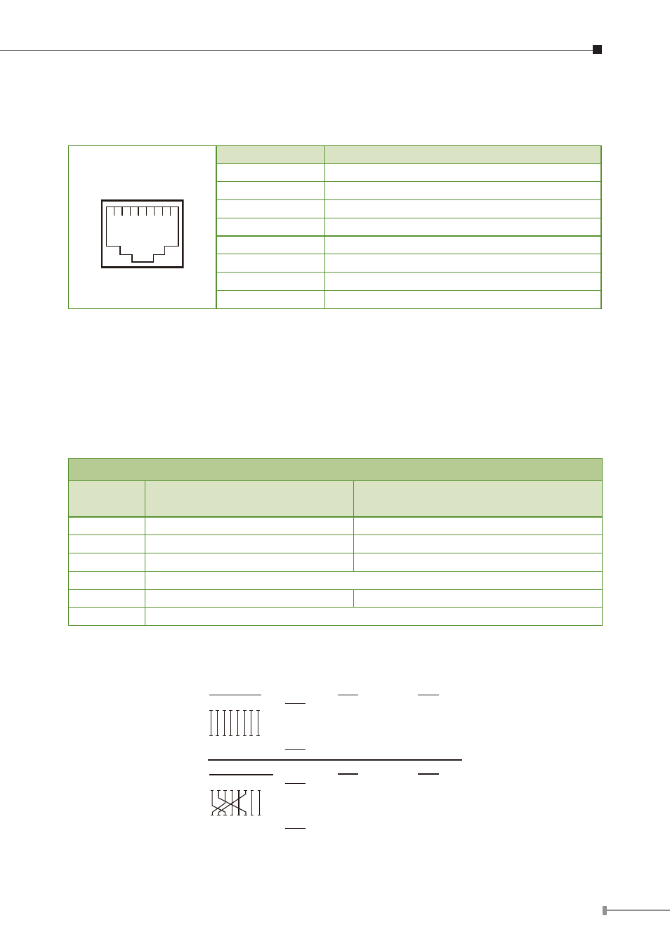
A.1 Data out PoE Switch RJ-45 Port Pin Assignments
1 2 3 4 5 6 7 8
PIN NO
RJ-45 SIGNAL ASSIGNMENT
1
Output Transmit Data +
2
Output Transmit Data –
3
Receive Data +
4
Negative Power –
5
Negative Power –
6
Receive Data –
7
Positive Power +
8
Positive Power +
A.2 10/100Mbps, 10/100Base-TX
When connecting Switch to another Fast Ethernet switch, a straight or crossover
cable might necessary. Each port of the Switch supports auto-MDI/MDI-X detection.
That means you can directly connect the Switch to any Ethernet devices without
making a crossover cable. The following table and diagram show the standard RJ-
45 receptacle/ connector and their pin assignments:
RJ-45 Connector pin assignment
Contact
MDI
Media Dependant Interface
MDI-X
Media Dependant Interface-Cross
1
Tx + (transmit)
Rx + (receive)
2
Tx – (transmit)
Rx – (receive)
3
Rx + (receive)
Tx + (transmit)
4, 5
Not used
6
Rx – (receive)
Tx – (transmit)
7, 8
Not used
There are 8 wires on a standard UTP/STP cable and each wire is color-coded. The
following shows the pin allocation and color of straight cable and crossover cable
connection:
Straight Cable
Cross Over Cable
SIDE 1
SIDE 1
SIDE 2
SIDE 1
SIDE 2
1 2 3 4 5 6 7 8
1 2 3 4 5 6 7 8
1 2 3 4 5 6 7 8
1 2 3 4 5 6 7 8
SIDE 2
1 = White/Orange
2 = Orange
3 = White/Green
4 = Blue
5 = White/Blue
6 = Green
7 = White/Brown
8 = Brown
1 = White/Orange
2 = Orange
3 = White/Green
4 = Blue
5 = White/Blue
6 = Green
7 = White/Brown
8 = Brown
SIDE 1
SIDE 2
1 = White/Orange
2 = Orange
3 = White/Green
4 = Blue
5 = White/Blue
6 = Green
7 = White/Brown
8 = Brown
1 = White/Green
2 = Green
3 = White/Orange
4 = Blue
5 = White/Blue
6 = Orange
7 = White/Brown
8 = Brown
Figure A-1: Straight-Through and Crossover Cable
Please make sure your connected cables are with same pin assignment and color
as above picture before deploying the cables into your network.