Avago Technologies MegaRAID SAS 9260-16i User Manual
Page 8
Page 8
LSI Corporation Confidential
|
June 2010
MegaRAID SAS 9260-16i RAID Controller Quick Installation Guide
Controller Installation
4. Install the RAID Controller
Insert the controller into a PCI Express slot on the motherboard, as shown in
. Press down gently, but firmly, to seat the card correctly in the slot. Secure
the RAID controller to the computer chassis with the bracket screw.
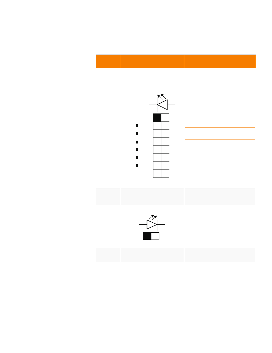
J4A4
LED Locate and Fault Indication
header
Ports 8-11
Ports 12-15
2x8-pin header
Connects to an LED that indicates whether
a drive is in a fault condition. There is one
LED per port. When lit, each LED indicates
the corresponding drive has failed or is in
the Unconfigured-Bad state.
The LEDs function in a direct-attach
configuration (there are no SAS
expanders). Direct attach is defined as a
maximum of one drive connected directly
to each port.
NOTE: This header is used for RAID
controllers with internal SAS ports only.
J4B2
x4 SAS Ports 12-15 internal
connector
SFF-8087 x4 internal mini SAS connector
Connects the controller by cable to SAS
drives or SATA 2 drives.
J5A2
Write pending LED header
2-pin connector
Connects to an LED that indicates when
the data in the cache has yet to be written
to the storage devices. Used when the
write-back feature is enabled.
J5B3
Universal Asynchronous
Receiver/Transmitter (UART)
debugging
4-pin connector
Reserved for LSI use.
Table 1:
Jumpers and Connectors (Continued)
Jumper/
Connector
Type
Description
J4A4
PORT 8
PORT 15
+ve
-ve
k
a
J5A2
a
k
+ve
-ve