Table 1, J1b1 port 0 port 7 – Avago Technologies MegaRAID SAS 9260-16i User Manual
Page 6
Page 6
LSI Corporation Confidential
|
June 2010
MegaRAID SAS 9260-16i RAID Controller Quick Installation Guide
Controller Installation
Table 1:
Jumpers and Connectors
Jumper/
Connector
Type
Description
J1A2
Universal Asynchronous
Receiver/Transmitter (UART) for the
Expander
4-pin connector
Reserved for LSI use.
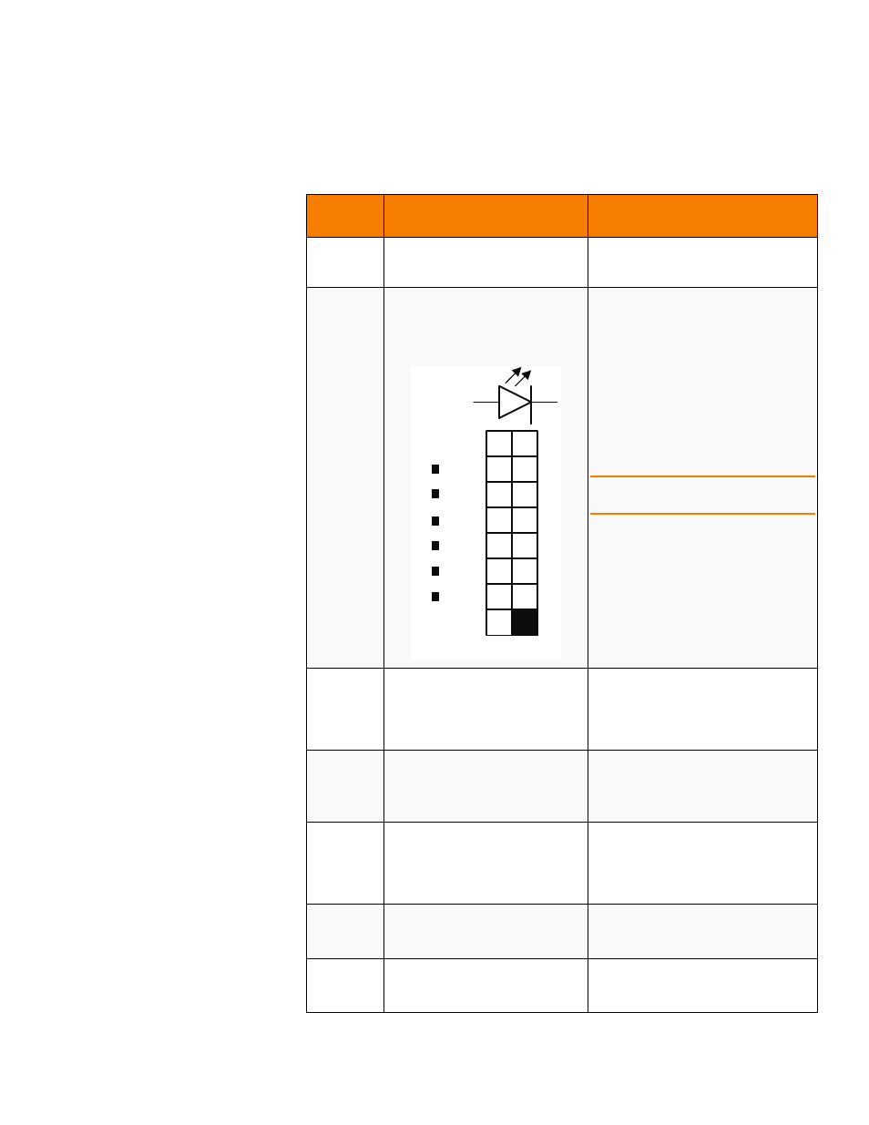
J1B1
LED Locate and Fault Indication
header
Ports 0-3
Ports 4-7
2x8-pin connector
Connects to an LED that indicates whether
a drive is in a fault condition. There is one
LED per port. When lit, each LED indicates
the corresponding drive has failed or is in
the unconfigured-bad state.
The LEDs function in a direct-attach
configuration (there are no SAS
expanders). Direct attach is defined as a
maximum of one drive connected directly
to each port.
NOTE: This header is used for RAID
controllers with internal SAS ports only.
J1B3
Advanced Software Hardware Key
header
2-pin header
Enables support for selected advanced
features, which include recovery,
CacheCade, FastPath, and SafeStore disk
encryption.
J1C1
IPMI-style I
2
C connector
3-pin connector
Supports SES (SCSI enclosure services)
over I
2
C through an internal I
2
C backplane
cable.
J1L1
Remote Battery Backup connector
(on the backside of the controller)
20-pin connector
Connects the LSIiBBU07 intelligent Battery
Backup Unit or the LSIiBBU08 intelligent
Battery Backup Unit remotely to the RAID
controller.
J2B1
x4 SAS Ports 0-3 internal connector
SFF-8087 x4 internal mini SAS connector
Connects the controller by cable to SAS
drives or SATA 2 drives.
J2B2
x4 SAS Ports 4-7 internal connector
SFF-8087 x4 internal mini SAS connector
Connects the controller by cable to SAS
drives or SATA 2 drives.
J1B1
PORT 0
PORT 7
+v e
- v e
a
k