Avago Technologies MGA-81563 User Manual
Page 3
Page 3 of 6
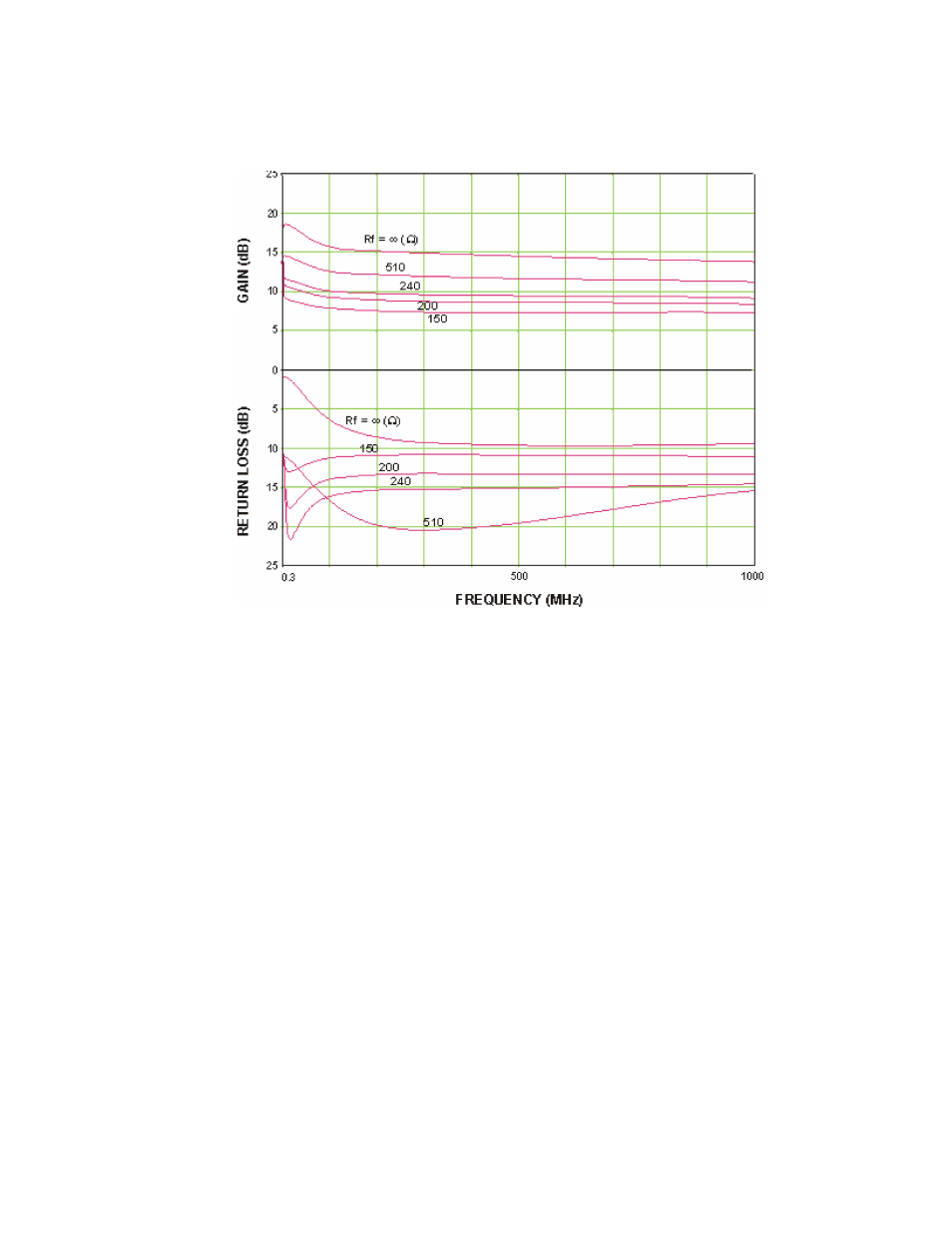
shows both gain and input return loss from 300 kHz to 1 GHz with several
values of feedback resistance. Performance without any external feedback is
also shown for comparison.
Figure 3. Test Results with External Feedback.
A value for the feedback resistor between 240 and 510 ohms provides a
balanced trade-off between improved input match and reduction in gain. The
aberration in performance at the lowest frequency end of the plots is due to
the 500 pF capacitor (two 1000 pF capacitors in series) in the feedback loop.
A higher value for Cf would further extend the low end response.
It would be theoretically possible to limit the effect of the feedback, and thus
the reduction in gain, to only the low frequency portion of the band by
adding a series inductor to the feedback loop. In practice the combination of
high value capacitors (e.g., in the mF range) and their associated parasitics
in combination with the inductor would lead to undesirable resonances.
The high output power feature of the MGA-82563 is not affected by the
external feedback approach. An output power of 17.7 dBm at 1-dB gain
compression was measured on this circuit using a feedback resistor of 240
ohms. (This measurement was made at 40 MHz due to the limitation of
external bias tees used in the particular power test system.)
Shunt Input Resistor Method