Iv — controls, terminations, and adjustments – KEPCO RAX 1500W User Manual
Page 3
092200
228-1229 REV 2
3
KEPCO, INC. !"! 131-38 SANFORD AVENUE !" FLUSHING, NY. 11352 U.S.A.!" TEL (718) 461-7000!"! FAX (718) 767-1102!!
http://www.kepcopower.com "! email: [email protected]
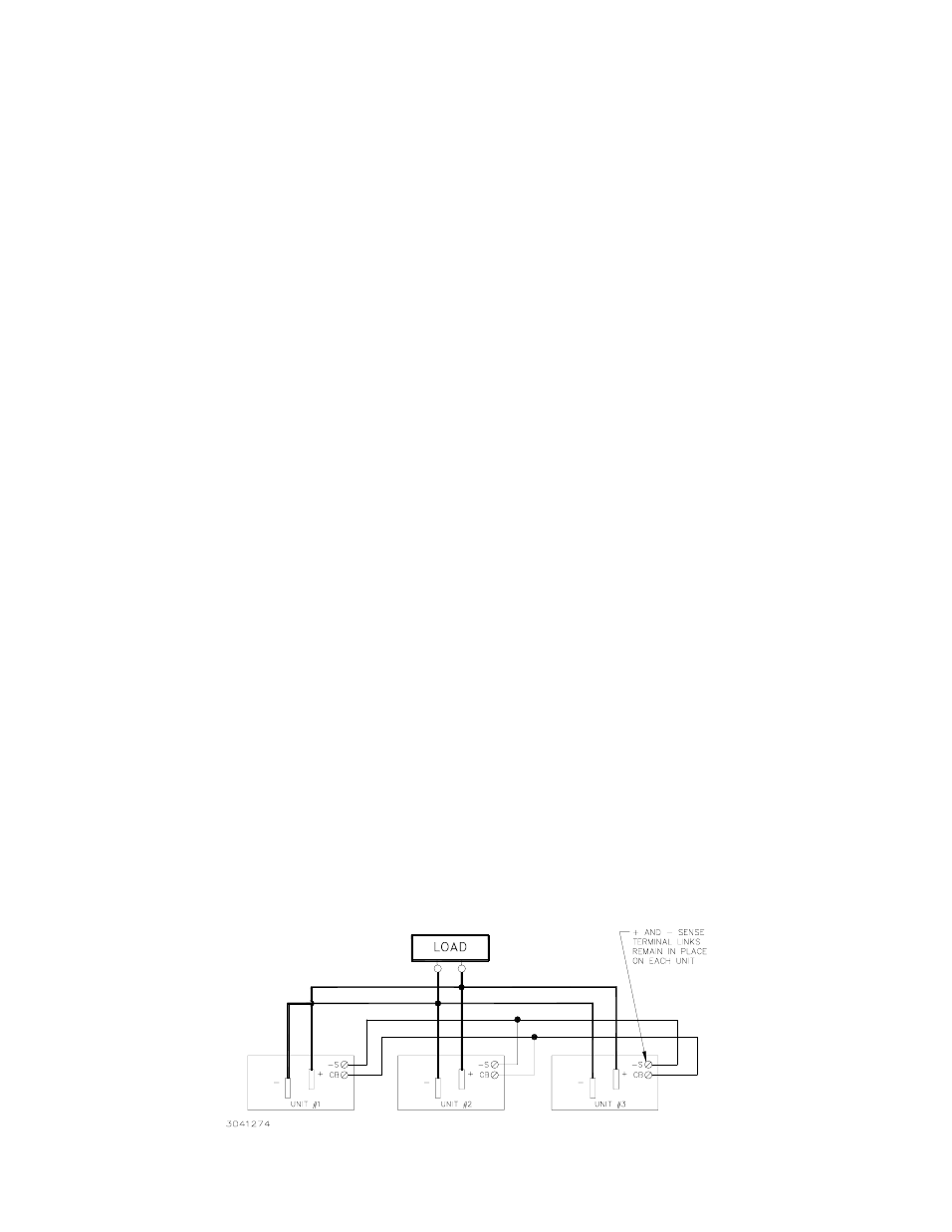
PARALLEL CONNECTION:
Refer to Figure 2. Connect the Current Balance (CB) terminals as shown.
SELECTING INPUT VOLTAGE:
Input voltage is selected with a shorting link. Refer to Figure 1. The power supply is delivered for 115V a-c
operation.
Remove shorting link from left side barrier strip terminals
to operate the unit from a nominal 220-240V a-c or 320V d-c source.
REMOTE TURN-ON TURN-OFF
When power is on at the source the unit may be turned on or off with the remote control feature. The output of the
remote turn-on/off terminals operates at TTL logic levels (2.4V “high” from the unit and 0.0 to 0.4V short to ground, “low”). The unit is turned off by
bringing the remote turn-on/off terminals to “low” logic level with a switch or solid state device. If the remote on/off feature is not desired, the terminals
should be left open.
VOLTAGE ADJUSTMENT:
Refer to Figure 3. Voltage is adjusted from the front panel as marked. To adjust voltage, first place the unit under an
operating load, then monitor the + and - sense terminals with a precision voltmeter and turn the voltage control to the desired operating value. Refer
to Table 1 for Adjustment Range.
FUSE PROTECTION:
The user is provided with a 50A input fuse for protection during normal operation. The fuse is accessible after the cover is
removed; refer to Figure 3. The following fuse is specified.
KEPCO P/N: 541-0105 or Manufacturer Fuji P/N CR2LS-50/UL, 50A, 250V ;
The Unit also employs internal fuses for safety and protection against catastrophic failures. These fuses are only accessible when the unit is disas-
sembled for repair. Two soft start fuses Kepco P/N 541-0104, or manufacturer Uchihashi P/N 121, 2A, 250V; and a switcher fuse Kepco P/N 541-
0048 or Manufacturer Bussman ABC 15A, 15A, 250V.
IV — CONTROLS, TERMINATIONS, AND ADJUSTMENTS
The following controls, terminations and adjustments are available to the user.
D-C OUTPUT.
The output appears on heavy bus bars at the front center of the unit.
+ SENSE, – SENSE.
These leads compensate for voltage error and must be placed directly on the load terminals for the most accurate error track-
ing. The unit is delivered with removable links on the front panel that connect the sense leads directly to the output bus terminals. The links may be
removed and the sense leads connected directly to the load. This compensates for voltage drop in the leads to the load. Refer to Figure 1
MONITOR.
The monitor leads are placed across the output and may be connected to a precision voltmeter to monitor output.
MONITOR LIGHT.
This a a green LED that is ON when output is present.
VOLTAGE ADJUST (R156).
This potentiometer is mounted just below the monitor light. It is used to adjusted the output voltage within the range
specified in this manual.
REMOTE CONTROL (RC).
The RC leads cause the unit to turn off when the leads are brought to ground potential with a mechanical switch or TTL
control. Use of remote control is optional.
REMOTE VOLTAGE ADJUST (RV).
A potentiometer placed between the RV terminal and the + Sense terminal may be used to adjust voltage
from a remote location. Its use is optional. For RAX 48-30K use a 10K ohm external potentiometer. All other models use 5K ohm. When the external
voltage adjustment feature is used the panel voltage adjustment should be turned fully clockwise.
CURRENT BALANCE (CB).
These terminals are used when up to three RAX 1500 units are connected in parallel. When using a parallel connec-
tion the CB terminals are connected together as shown in Figure 2. Output voltage tolerance 5% per unit, current balance tolerance 10% max., out-
put current range nominal 20-90%.
A-C INPUT VOLTAGE.
Labelled terminals are provided on the front panel for selecting input voltage.
V - SHUT-DOWN PROTECTION AND REMOTE CONTROL
Turn-off or shutdown takes place under the following conditions:
REMOTE CONTROL:
Bringing the RC terminals together with either a mechanical switch or logic control causes the unit to turn off and remain off
as long as the condition is maintained. Output resumes immediately when the remote terminals are reopened.
FAN FAILURE:
The Unit will not operate unless both fans are operating. If either fan stops rotation, the unit shuts down and remains shut down as
long as the condition exists.
OVERCURRENT AND SHORT CIRCUIT:
Overcurrent causes an abrupt voltage drop. Current remains at the maximum value. When the output
voltage falls to less than 70% of nominal for 20 seconds, the output is shut down but the fans remain operating. If the cause of the overcurrent is
removed within 20 seconds, output returns to normal. If overcurrent remains beyond 20 seconds, a restart cycle is required as described in the fore-
going. The unit must remain off for 30 seconds before restarting.
OVERTEMPERATURE:
A thermistor heat sensor is located in the switcher heatsink. When heatsink temperature reaches 120° C, the output cuts
off and remains off as long as the temperature remains above 120° C.
FIGURE 2. PARALLEL CONNECTION USING CURRENT BALANCE