Figure 2. connecting the load with error sensing – KEPCO RAX 300W User Manual
Page 3
KEPCO, INC. !"! 131-38 SANFORD AVENUE !" FLUSHING, NY. 11352 U.S.A.!" TEL (718) 461-7000!"! FAX (718) 767-1102!!
http://www.kepcopower.com "! email: [email protected]
092200
228-1228 REV 2
3
VIBRATION: Three Axes: 5-10 Hz., 10 mm amplitude; 10-55 Hz., 2G
SHOCK: Three axes, 20g, 11 ms ±5msec pulse duration
EMI CONDUCTED: FCC Class A
SAFETY: All units designed to meet UL 1950D3, UL 478, CSA
Electrical Bulletin 1402C, VDE 0806, TÜV Rheinland EN60950 and
IEC 950 Safety Standards. RAX are CE marked per the Low Voltage
Directive (LVD), EN60950. [The standards do not apply with DC input
operation].
REMOTE ERROR SENSING: 5-60K models, up to 0.25V per load wire.
All other models, up to 0.4V per load wire. The power supply is factory
set with links in place.
REMOTE CONTROL ON/OFF:
“High,” 2.4V-24V (or open), unit ON
“Low,” 0.0V-0.4V (or closed), unit OFF
When Remote Control (RC) is at “Low” level, the output voltage
remains Vo <0.5V.
Vo <5.0% of nominal output for 12, 15, 24, 28 and 48 volt models
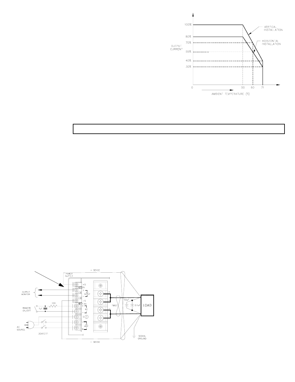
III — OPERATION UNIT WILL NOT WORK WITH SENSE LEADS DISCONNECTED (SEE FIG. 2).
INSTALLING THE POWER SUPPLY: Refer to Figure 4. The unit may be mounted on one of the three mounting surfaces.
Mounting holes are provided for each mounting style. The air surrounding the power supply must not exceed the ambient val-
ues given in the graph in Figure 1.
CONNECTING AND SWITCHING THE LOAD: The load is connected as shown in Figure 2. Error sensing may be done at
the load terminals to compensate for voltage loss in the connecting wires. The jumper links must therefore be removed from
the sense terminals.
SELECTING INPUT VOLTAGE: Input voltage is selected with a jumper. Refer to Figure 3. The power supply is delivered
for 120V a-c operation. Change the jumper to the position marked “230V” to operate the unit from a nominal 220-240V a-
c or 320V d-c source.
VOLTAGE ADJUSTMENT: The unit is provided with a voltage adjustment control. To adjust voltage, first place the unit under
an operating load, then monitor the + and - sense terminals with a precision voltmeter and turn the voltage control to the
desired operating value. Refer to Table 1 for Adjustment Range.
CHANGING FUSE: Remove the cover to replace a fuse (10A, 250V). Refer to Figure 3.
The fuse holder will accept two sizes, either:
KEPCO P/N: 541-0125 or Manufacturer LITTLEFUSE P/N 314010; 10A, 250V (1/4” x 1-1/4”)
KEPCO P/N: 541-0099 or Manufacturer LITTLEFUSE P/N type F 217010; 10A, 250V (5mm x 20mm)
REMOTE TURN-ON TURN-OFF When power is on at the source the unit may be turned on or off with the remote control fea-
ture. The output of the remote turn-on/off RC (remote control) terminals operates at TTL logic levels (2.4V-24V “high” and 0.0
to 0.4V “low”). The unit is turned off by bringing the RC terminals to “low” logic level with a switch or solid state device. If the
remote on/off feature is not desired, the terminals should be left open.
FIGURE 2. CONNECTING THE LOAD WITH ERROR SENSING
(SEE NOTE)
LINKS
3041271(2)
FIGURE 1. TEMPERATURE DERATING
NOTE:
THE SENSE LEADS MUST NEVER BE DISCONNECTED FROM
THE OUTPUT. IF THE SENSE LEADS ARE ALLOWED TO FLOAT
FREE OF THE OUTPUT, THE OUTPUT VOLTAGE WILL RISE TO
THE OVERVOLTAGE POINT AND THE UNIT WILL SHUT DOWN.
•
FOR REMOTE SENSING CONNECT THE SENSE TERMI-
NALS TO THE LOAD AS SHOWN, AND REMOVE THE TWO
SENSING LINKS.
•
FOR LOCAL SENSING LEAVE THE SENSING LINKS IN
PLACE AND CONNECT THE LOAD DIRECTLY TO THE BUS
BAR.