Installation, Input connections, Load connections – KEPCO KLP Series Quick Start Guide, P/N 228-1616, Rev 6 User Manual
Page 5: Input connections load connections
070312
228-1616 REV 6
5
KEPCO, INC. 131-38 SANFORD AVENUE FLUSHING, NY. 11355 U.S.A. TEL (718) 461-7000 FAX (718) 767-1102
http://www.kepcopower.com email: [email protected]
INSTALLATION.
Install units in a 19 inch-wide rack. Optional slides may be used. Leave the front
and rear panels clear of obstructions to ensure adequate cooling. For parallel, series and master-slave
configurations, refer to the User Manual.
INPUT CONNECTIONS. Wire the mating source power connector provided (142-0381) for your input
mains (see Table 5 for mains voltage range). The user must provide a properly sized and rated mains
lead (line cord) and service with a current rating compatible with the anticipated input current. Line cords
available as accessories are listed in Table 3. Plug the source power connector into the source power
inlet connector at the rear panel.
LOAD CONNECTIONS. Connect the load to the (+) and (–) DC OUTPUT terminals on the rear panel
(Figure 2). (+M) and (–M) outputs are for connection of external monitoring equipment such as a DVM,
oscilloscope, etc.
Configuration of local sensing is facilitated by pre-installed jumpers which configure the unit for local
sensing.as shown in Figure 2.
NOTE: Output Sense lines must be connected for proper operation, either locally, or at the load
(remote).
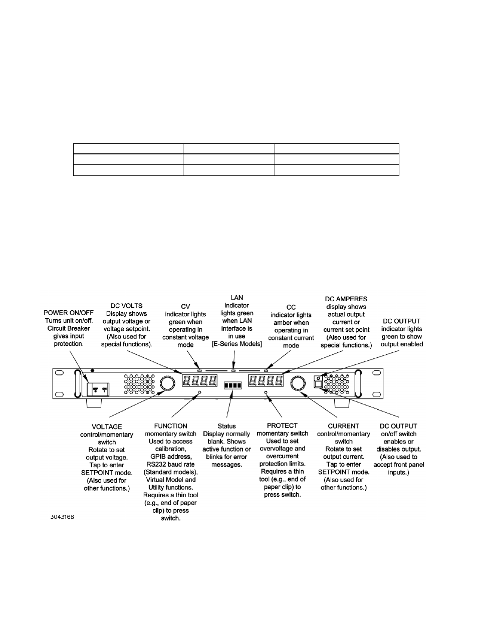
FIGURE 1. KLP SERIES, FRONT PANEL CONTROLS AND INDICATORS
TABLE 5. INPUT CURRENT SERVICE RATING AND CONDUCTOR SIZES
MAINS VOLTAGE RANGE
CURRENT SERVICE RATING
CONDUCTOR SIZE
100 - 132V a-c, 50/60Hz
20 Amp
#12AWG [2,0 mm²]
180 - 265V a-c, 50/60Hz
15 Amp
#14AWG [1,6 mm²]