KEPCO FAK 25W Series User Manual
Kepco
©1996, KEPCO, INC
Data subject to change without notice
228-1160
1
I N S T R U C T I O N M A N U A L
FAK
KEPCO
KEPCO, INC. !"! 131-38 SANFORD AVENUE !" FLUSHING, NY. 11352 U.S.A.!" TEL (718) 461-7000!"! FAX (718) 767-1102!!
http://www.kepcopower.com "! email: [email protected]
An ISO 9001 Company.
KEPCO 25 WATT HIGH FREQUENCY
SWITCHING POWER SUPPLIES
I — INTRODUCTION
The Kepco FAK 25 Watt Series low profile high frequency switching power supplies employ forward conversion and operate at 80% efficiency
with either a-c or d-c input. A thermistor soft-start circuit limits start-up surge. Surface mount technology permits efficient compact topology for
minimum mounting space. Four models may be selected for outputs of 5, 12, 15 or 24V. A green “POWER OK” light is provided. A steel cover
(Model CA 22) is available as an option. Output voltage may be adjusted with a trimmer accessible near the input-output barrier strip. When
the input is cut off, the output is maintained for 20–30 milliseconds (30 milliseconds typical). EMI filtering meets FCC Class B rating. Table 1
contains specifications for each model of the FAK 25 Watt Series. Environmental specifications for each model are the same.
II — SPECIFICATIONS
The following specifications apply to FAK 25 Watt Series models.
INPUT:
Voltage: 115V a-c nominal; Range 85-132V a-c; 110-170V d-c.
Frequency: Nominal 50-60 Hz; Range 47-440Hz (at 440Hz leakage current exceeds UL safety spec. limit).
Current: 0.5A typ., 0.65A max. (nominal output at rated load @25° C).
Initial Turn-on Surge: 43A max. (one-half of first input cycle).
STABILIZATION:
Source Effect: 0.6% typ.; 2.0% max. from minimum to maximum input.
Load Effect: 1.2% typ.; 3.0% max. (range: 10%-100% load).
Temperature Effect: 0.6% typ.; 2.0% max. (range: 0
o
to 50
o
C).
Combined Effect: ±1.0% typ.; ±3.0% max. (includes source, load, and temperature effects).
Drift: 0.1% typ.; 0.5% max. (1/2 hr—8 hr at 25
o
C).
RECOVERY CHARACTERISTICS:
A step load change from 50% to 100% produces less than +4% output excursion. Recovery occurs to
within +1% of the original setting in <1 ms (t
r
or t
f
equal to or greater than 50
µ
sec at load change).
START-UP TIME:
100 ms. maximum.
HOLD-UP TIME:
30 ms. typ. (20 ms. min).
DIELECTRIC STRENGTH:
Between input and output: 2KV a-c for one minute.
Between input and ground terminals: 2KV a-c for one minute.
LEAKAGE CURRENT
(UL method, 115V a-c, 50-60Hz): 0.5 mA maximum.
SAFETY:
UL 478 recognized; CSA 1402 certified.
EMI:
Designed to meet FCC 20780. Class B.
VIBRATION:
(non-operating, one hour on each one of the three axes):
5-10 Hz, 10 mm amplitude.
10-55 Hz, 2g acceleration.
SHOCK:
(non-operating, one-half sinusoidal pulse, three shocks to each axis):
Acceleration: 20g
Duration: 11ms +5ms
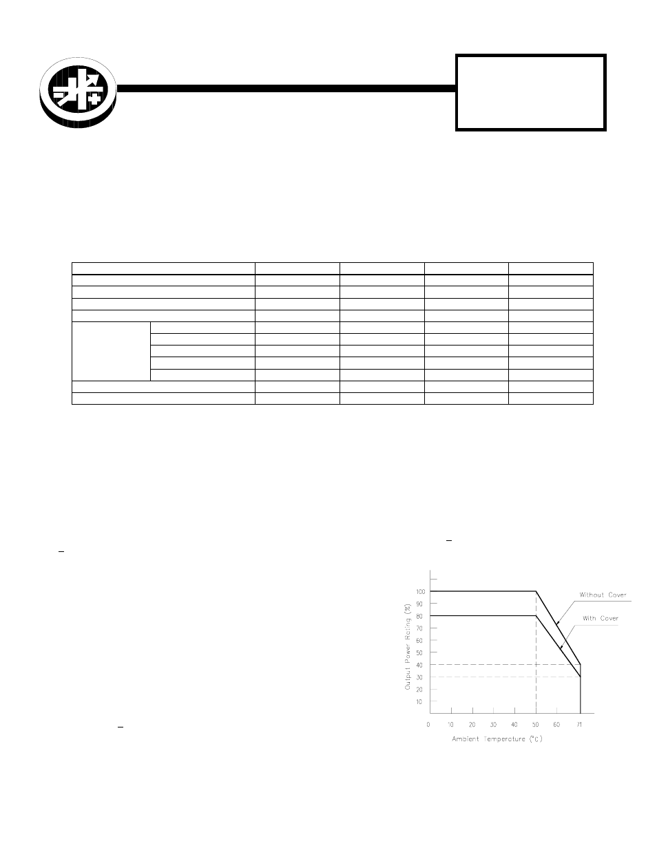
OPERATING TEMPERATURE:
See Figure 1.
STORAGE TEMPERATURE:
-40
o
C to +75
o
C.
OPERATING AND STORAGE RELATIVE HUMIDITY:
20%–95% (non-condensing).
FUSE:
Medium acting 2.5A, 125V; (5.2 x 20mm), Nagasawa P/N GGS2.5A; Kepco P/N 541-0058.
WARRANTY:
1 year.
TABLE 1. OUTPUT RATINGS AND SPECIFICATIONS, FAK 25W SERIES
MODEL
FAK 5-5K
FAK 12-2.1K
FAK 15-1.7K
FAK 24-1.1K
OUTPUT VOLTS, d-c (NOMINAL)
5.0V
12.0V
15.0V
24.0V
ADJUSTMENT RANGE
4.5-5.5V
10.8-13.2V
13.5-16.5V
21.6-26.4V
OUTPUT CURRENT (NOMINAL)
5.0A
2.1A
1.7A
1.1A
OUTPUT POWER (MAXIMUM)
25.0W
25.2W
25.5W
26.4W
RIPPLE
AND
NOISE
(mV p-p)
0-50°C
10-100% LOAD
source (typ)
10
10
10
10
source (max)
30
30
30
30
switching (typ)
30
30
30
30
switching (max)
70
70
70
80
spike noise (d-c—50MHz)
120
190
220
310
OVERVOLTAGE SETTING 25 °C, NOM. INPUT
6.0-6.9V
13.7-15.7V
17.0-19.0V
27.0-30.5V
OVERCURRENT SETTING 25 °C, NOM. INPUT
5.5-7.5A
2.3-3.3A
1.9-2.8
1.2-1.8
FIGURE 1. OUTPUT POWER VS. AMBIENT
TEMPERATURE
3040229