Figure 6. utilities window, Programmer reference, 1 visa instrument driver functions – KEPCO BOP VISA Driver (Universal, GPIB) User Manual
Page 6
6
BOP-VISA 042114
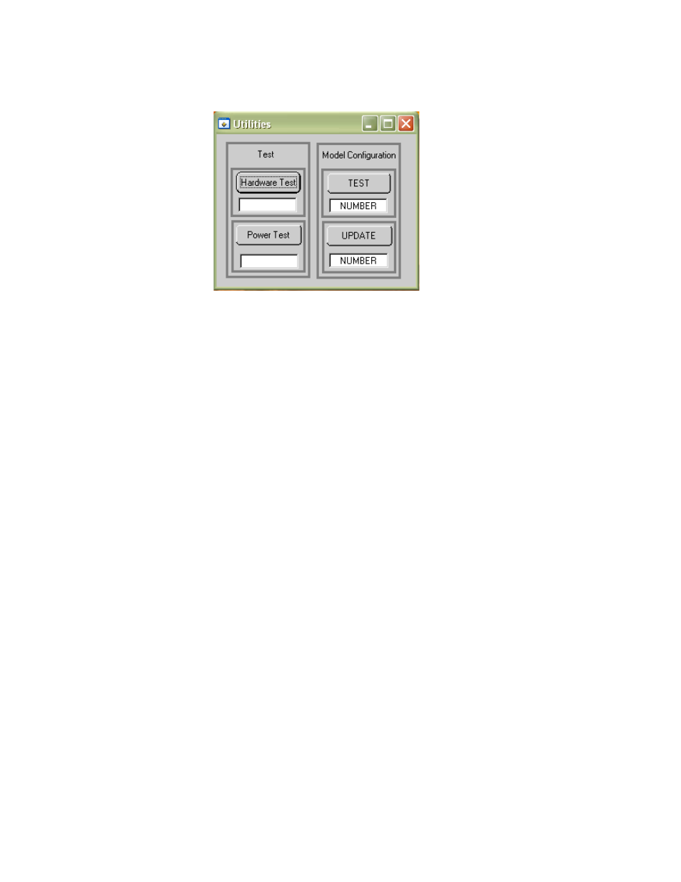
The Utilities button opens the Utilities window (Figure 6). The Hardware Test button tests the validity of
system parameters (e.g., CRC).
FIGURE 6. UTILITIES WINDOW
The Power Test button performs a full power test by first testing maximum voltage output, then testing
minimum voltage output.
Model Configuration. Special models of BOP power supplies and BIT interface cards are identified by a
5-digit suffix. A text file supplied with the driver, optionxxxxx.txt (where xxxxx = the 5-digit suffix) identifies
how the special unit has been configured using the control commands described in the Theory of Opera-
tion section of the applicable technical manual. When the 5-digit number is entered in the Model Configura-
tion TEST NUMBER window, and the TEST button is pressed, the optionxxxxx.txt file is scanned and the
configuration is verified, resulting in either PASSED or TEST FAILS displayed in the TEST NUMBER win-
dow. NOTE: The TEST button must also be used to reconfigure special shutdown requirements each time
the VISA application is started.
Entering the 5-digit suffix in the Model Configuration UPDATE TEST window and clicking the UPDATE but-
ton, restores the factory set special options using the optionxxxxx.txt file. When directed by factory sup-
port, this feature can be used to change the configuration of the unit to accommodate customer requests or
firmware upgrades.
The Reset button on the Main Panel (Figure 2) resets the unit to the power up defaults: output voltage and
current set to zero, and output off.
The QUIT button on the virtual panel (Figure 2) is used to exit the sample VISA application.
2. PROGRAMMER REFERENCE
2.1 VISA INSTRUMENT DRIVER FUNCTIONS
Kepco’s BOP VISA instrument driver provides programming support for Kepco’s BOP Power Supply (VISA
I/O). It contains functions for opening, configuring, taking measurements from, test, calibration and closing
the instrument. To successfully use this module, the instrument must be connected to the GPIB and the
GPIB address supplied to the initialize function must match the GPIB address of the instrument.