Caution precaution, Figure 47: wiring diagram, Flashes diagnostic fault codes fault condition – Thermo Pride Spirit Gas TP9C Modulating ECM 97.5% User Manual
Page 43: Legend, Legende, Integrated control board, Lo comp hi comp o dhum y1 y/y2 w r g c
1083292-UIM-A-0114
Johnson Controls Unitary Products
43
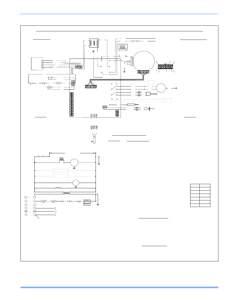
SECTION XII: WIRING DIAGRAM
FIGURE 47: Wiring Diagram
POWER SUPPLY 115-1-60
GAS VALVE
TO AIR CONDITIONER
CONTROLS
ROOM
THERMOSTAT
COMMON T'STAT CONNECTION
Y2
Y
R
C
G
Y1
W
W
Y1
G
C
R
Y
Y2
IDM
EAC
HUMIDIFIER
MOT
GND
(EN TERRE)
C
NO
IGNITOR
NO
PS1
C
GRD
COM
120V
24V SEC
PRI
XFMR
LS
ROS1
ROS2
BLK
24V
120V
COM
GRN
WHT
GAS
VALVE
WHT
WHT
2
1
GRN
BLK
BLK
WHT
INTEGRATED
CONTROL
BOARD
RED/GRN
RED/GRN
RED
BLU
BRN
TAN
TAN
GRY
GRY
PRP
IGNITOR
IDM
FLAME
SENSOR
LS
NO
C
DS
115VAC LINE
115VAC NEUT.
ID PLUG
1
2
XFMR
HUMIDIFIER
AIR
CLEANER
ORG
ORG
NO
C
PS1
LO COMP
HI COMP
O
DHUM
Y1
Y/Y2
W
R
G
C
120VAC
NEUTRAL
GROUND
120VAC
XFORMER
NEUTRAL
XFORMER
MOTOR
MOTOR
FUSE
HUMDIFIER
NEUTRAL
NEUTRAL
NEUTRAL
NEUTRAL
HOT
EAC
HOT
HOT
HOT
IGNITER
INDUCER
EAC
FLAME ROD
24VAC
GND
GAS
PRIM LIMIT
AUX LIMIT
EXT
PRESSURE
SENSOR
RED/WHT
BLK/WHT
GRN/WHT
PRESSURE
SENSOR
GRN
BLK
RED
120VAC
LINE
LINE
NEUTRAL
THERMISTER
BLK
BLK
1
2
RED/BLK
RED/BLK
TEMPERATURE
SENSOR
MOTOR CONNECTOR
(1)GRN
(8)GRN
(3)GRN
(12)BRN
(10)BLK
(9)BRN
(15)BLU/WHT
(16)YEL/BLK
BLK
WHT
BLK
GRN
POWER
FACTOR
CHOKE
(NOT USED ON 1/2 HP MOTORS)
BLK
BLK
BLK
POWER
FACTOR
CHOKE
(NOT USED ON 1/2 HP MOTORS)
NO
PS2
C
WHT
BLK
AIR SW
GND
TX
RX
HOT
HOT
24VAC
OUT
GND
VCC
1
2
3
4
5
6
1
3
4
6
7
8
2
5
RED
ROS1
ROS2
RED
NO
C
PS2
RED
YEL
GRN
RED
BLU/WHT
ORG
TH
RXD
TXD
TR
MV TH
1
2
3
4
5
DS
ID Plugs
Wiring Diagram -97+% Modulating Condensing Furnace with ECM Motor
Flashes
Diagnostic Fault Codes
Fault Condition
Power Off
Normal Operation
Factory speedup mode
Normal Operation with call for cooling
Low flame sense current
Normal Operation with call for heat
Normal Operation, burner on at end of heat cycle
Reduced Airflow problem
High altitude installation OR vent, intake OR termination problem
Normal Operation with call for heat pump heating
Control Failure
Flame present with gas off
Check pressure switch wiring
Vent, intake, or termination problem
Airflow problem
Flame Rollout OR open fuse
Check gas valve wiring
Failed to light burners
Loss of flame during call for heat
Hot/Neutral reversed OR poor ground/neutral
Gas valve shorted "ON"
Check blower motor/wiring
ID plug missing OR not connected properly
None
Slow Green
Rapid Green
Slow Amber
Rapid Amber
2 Amber
3 Amber
4 Amber
5 Amber
6 Amber
Steady Red
1 Redf
2 Red
3 Red
4 Red
5 Red
6 Red
7 Red
8 Red
9 Red
10 Red
11 Red
12 Red
SERVICING THIS UNIT
OPEN ALL DISCONNECTS BEFORE
CAUTION
PRECAUTION
OUVREZ LES DISJONCTEURS AVANT
DE PROCEDER AVEC LE SERVICE
1042428-UWD-A-0413
Fault Code Retrieval
Note to Servicers
Unlike conventional systems, the wall thermostat does not simply turn this furnace off and on.
The furnace control calculates the demand and THE FURNACE BURNERS MAY CONTINUE TO
FIRE DURING PART OF THE THERMOSTAT "OFF" CYCLE.
Refer to the furnace instructions for further information.
To retrieve fault codes, push and release ERROR button on control board. The LED will flash the
last five error codes, beginning with the most recent. If there are no fault codes in memory, the LED
will give two green flashes. To clear the fault code memory, push and hold the ERROR button for
at least five seconds. The LED will give three green flashes when the memory has been cleared.
Notice - Only a qualified service technician should use this feature.
Fault code retrieval functions will work only if there are no active thermostat signals.
NOTES:
1. Si l'un des fils d'origine fourni avec ce four doit être remplacé, il doit être
remplacé avec le fil ayant un degré de température d'au moins
221 degrés F (105 degrés C ).
2. Seulement des matettes pour fil de cuivre.
NOTES:
1. If any of the original wire as supplied with the furnace must be replaced,
it must be replaced with wiring material having a temperature rating of
at least 221 degrees F (105 degrees C ).
2. Connectors suitable for copper conductors only.
DS -
LS -
ROS1 -
ROS2 -
PS1 -
PS2 -
XFMR -
MOT -
IDM -
Legend
Door switch
Primary limit switch
Rollout switch
Rollout switch
Pressure switch
Condensate pressure switch
Transformer
Circulating motor
Inducer motor
DS -
LS -
ROS1 -
ROS2 -
PS1 -
PS2 -
XFMR -
MOT -
IDM -
Legende
Commutateur de porte
Commutateur de limite
Commutateur de roulement
Commutateur de roulement
Commutateur de pression
Commutateur de pression,
condensation
Transformeur
Moteur soufflerie
D'induct moteur
MOT
Model
Colors
60B12
BRN/YEL
80B12
RED/YEL
80C16
BLU/YEL
100C16
BLK/YEL
100C20
GRN/YEL
120D20
PUR/YEL