Thermo Pride Spirit Gas TP9C Modulating ECM 97.5% User Manual
Page 12
1083292-UIM-A-0114
12
Johnson Controls Unitary Products
Annual Fuel Utilization Efficiency (AFUE) numbers are determined in accordance with DOE Test procedures.
Wire size and over current protection must comply with the National Electrical Code (NFPA-70-latest edition) and all local codes.
The furnace shall be installed so that the electrical components are protected from water.
SUPPLY VOLTAGE CONNECTIONS
1.
Provide a power supply separate from all other circuits. Install
overcurrent protection and disconnect switch per local/national
electrical codes. The switch should be close to the unit for conve-
nience in servicing. With the disconnect or fused switch in the OFF
position, check all wiring against the unit wiring label. Refer to the
wiring diagram in this instruction.
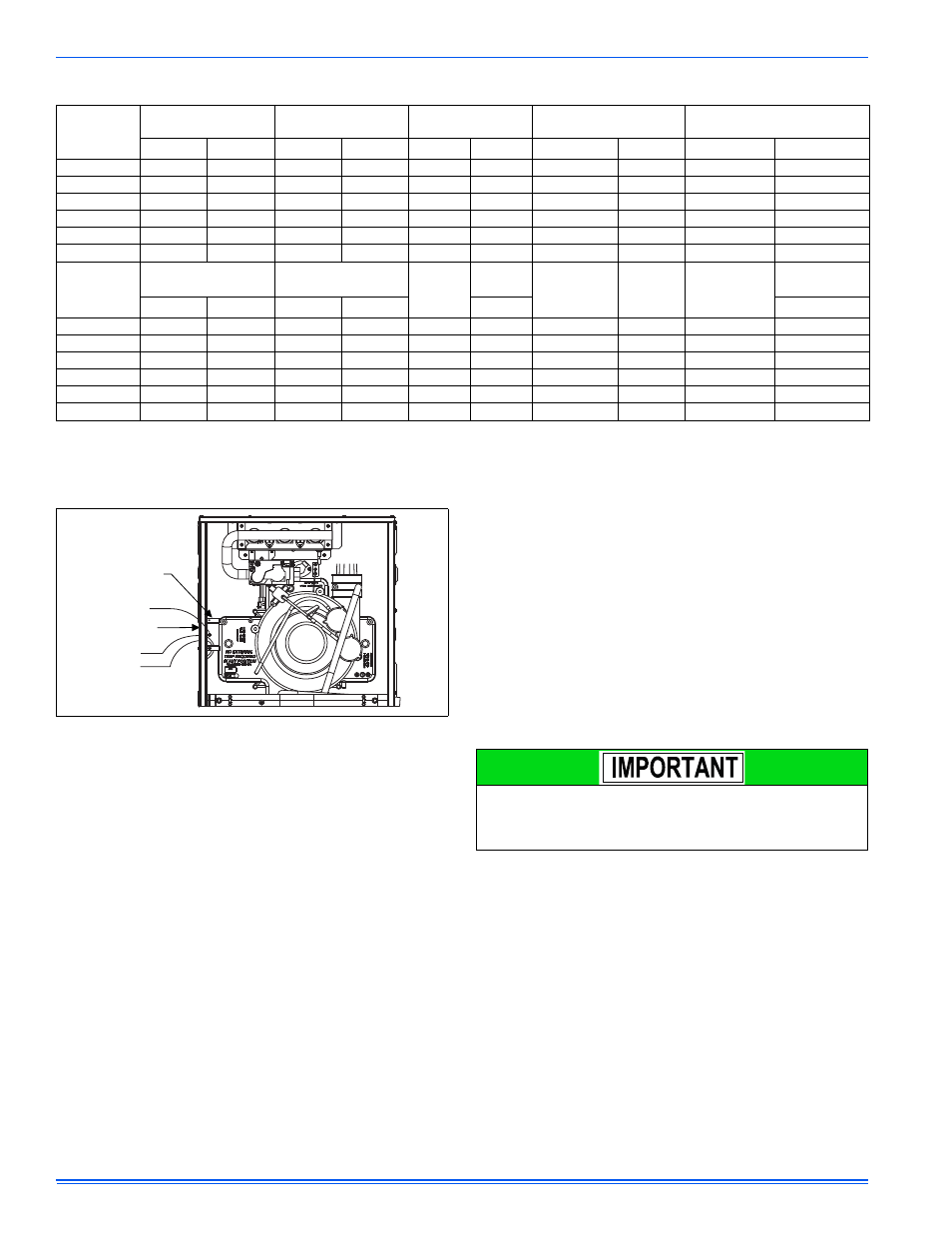
2.
Remove the screws retaining the wiring box cover. Route the
power wiring through the opening in the unit into the junction box
with a conduit connector or other proper connection. In the junc-
tion box there will be 3 wires, a Black Wire, a White Wire. Connect
the power supply as shown on the unit-wiring label on the inside of
the blower compartment door or the wiring schematic in this sec-
tion. The black furnace lead must be connected to the L1 (hot)
wire from the power supply. The white furnace screw must be con-
nected to neutral. Connect the power supply ground to the green
screw (equipment ground) An alternate wiring method is to use a
field provided 2” (5.1 cm) x 4” (10.2 cm) box and cover on the out-
side of the furnace. Route the furnace leads into the box using a
protective bushing where the wires pass through the furnace
panel. After making the wiring connections replace the wiring box
cover and screws. Refer to Figure 17.
3.
The furnace's control system requires correct polarity of the power
supply and a proper ground connection. Refer to Figure 17.
Table 6: Ratings & Physical / Electrical Data
BTUH/
Cabinet/CFM
Input
Max/Min
Output
Max/Min
Nominal
Airflow
Air Temp. Rise
Max Input
Air Temp. Rise
Min Input
MBH
kW
MBH
kW
CFM
m
3
/min
°F
°C
°F
°C
60B12
60/21
17.6/6.2
58/20
17.0/5.9
1200
34.0
40-70
22-39
20-50
11-28
80B12
80/28
23.4/8.2
77/27
22.6/7.9
1200
34.0
40-70
22-39
20-50
11-28
80C16
80/28
23.4/8.2
78/27
22.8/7.9
1600
45.3
40-70
22-39
20-50
11-28
100C16
100/35
29.3/10.2
97/34
28.4/10.0
1600
45.3
40-70
22-39
20-50
11-28
100C20
100/35
29.3/10.2
97/34
28.4/10.0
2000
56.6
45-75
25-42
25-55
13-31
120D20
120/42
35.1/12.3
116/40
34.0/11.7
2000
56.6
45-75
25-42
25-55
13-31
BTUH
Cabinet/CFM
Max. Outlet
Air Temp
Blower
Blower
Wheel
Size
AFUE
Max
Over-Current
Protect
Total Unit
Amps
Min. wire Size
(awg) @ 75 ft
one way
Approximate
Operating Wgt.
°F
°C
HP
Amps
%
Lbs (kg)
60B12
170
76.7
1/2
4.8
11 x 8
97.5
15
7.0
14
113 (51)
80B12
175
79.4
1/2
4.8
11 x 8
97.5
15
7.5
14
119 (54)
80C16
175
79.4
3/4
7.5
11 x 10
97.7
15
10.0
14
134 (61)
100C16
175
79.4
3/4
7.5
11 x 10
97.7
15
10.0
14
140 (64)
100C20
180
82.2
1
14.5
11 x 11
97.7
20
12.0
12
143 (65)
120D20
180
82.2
1
14.5
11 x 11
98.0
20
12.0
12
152 (69)
FIGURE 17: Electrical Wiring
Electrical Entry
Junction
Box
L1-Hot
Neutral
Connect ground
lead to screw
BLK
WHT
The power connection leads and wiring box may be relocated to the
opposite side of the furnace. Remove the screws and cut wire tie
holding excess wiring. Reposition on the opposite side of the furnace
and fasten using holes provided.