Air conditioner connections – Thermo Pride Spirit Gas TP9C Modulating ECM 97.5% User Manual
Page 14
1083292-UIM-A-0114
14
Johnson Controls Unitary Products
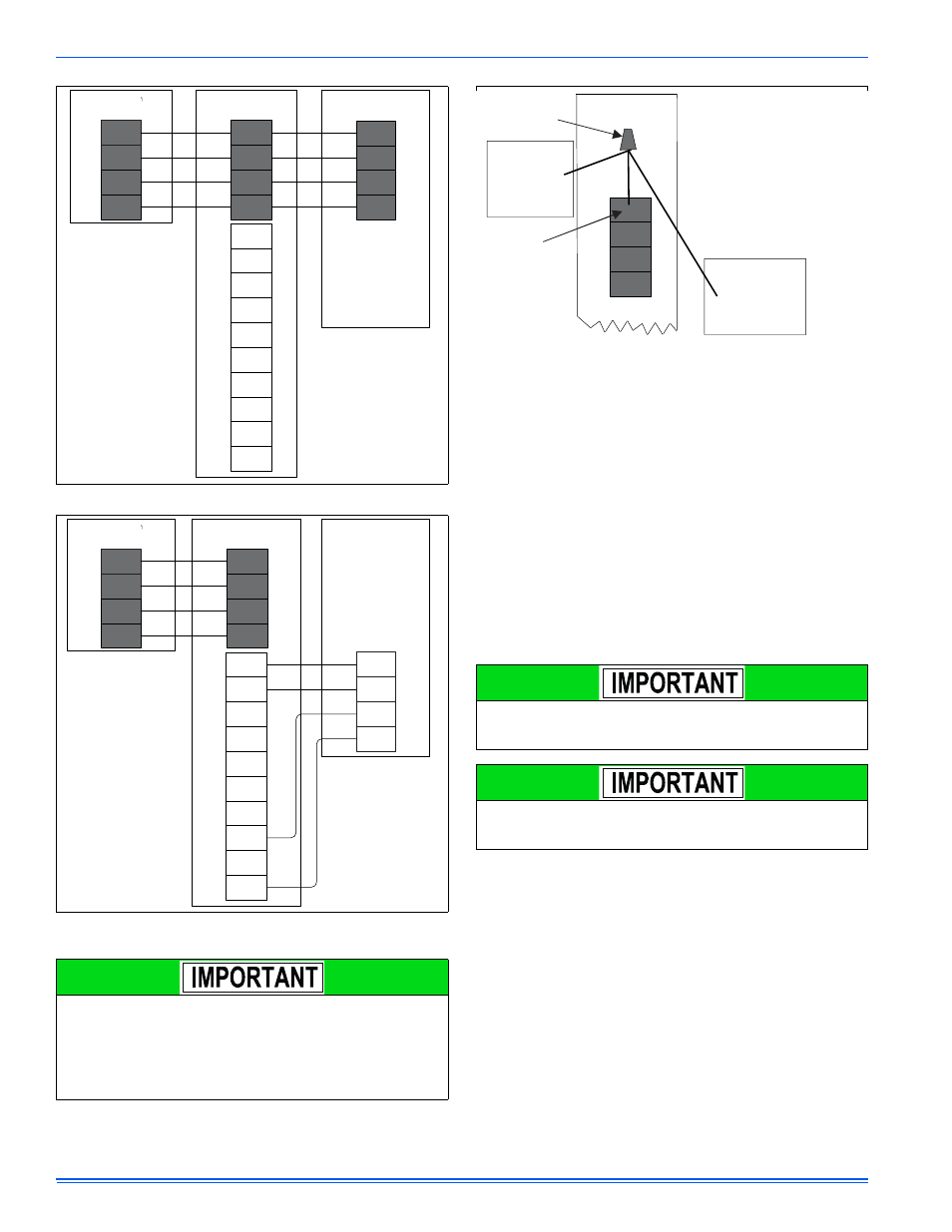
When connecting the Communicating Control (wall thermostat) and fur-
nace control to a non-communicating outdoor A/C or heat pump, use
the wiring diagram in Figure 20. The thermostat and furnace will be con-
nected exactly as shown above, but the conventional 24 volt R, C and
Y/Y2 terminals will be used to control the outdoor unit.
CONVENTIONAL LOW VOLTAGE CONTROL WIRING
CONNECTIONS
Install the field-supplied thermostat by following the instructions that
come with the thermostat. With the thermostat set in the OFF position
and the main electrical source disconnected, connect the thermostat
wiring from the wiring connections on the thermostat to the terminal
board on the ignition module, as shown in Figures 22-27. Electronic
thermostats may require the common wire to be connected. Apply
strain relief to thermostat wires passing through cabinet. If air condition-
ing equipment is installed, use thermostat wiring to connect the Y and C
terminals on the furnace control board to the proper wires on the con-
densing unit (unit outside).
The 24-volt, 40 VA transformer is sized for the furnace components
only, and should not be connected to power auxiliary devices such as
humidifiers, air cleaners, etc. The transformer may provide power for an
air conditioning unit contactor.
AIR CONDITIONER CONNECTIONS
This furnace may be used with single-stage or two-stage air condition-
ing units.
For Single-Stage A/C - Connect the low voltage wiring as shown in
Figure 22.
For Two-Stage A/C - Use a two-stage thermostat, connect the low volt-
age wiring as shown in Figure 23.
For Two-Stage A/C using a Single-Stage Thermostat - connect the
low voltage wiring as shown in Figure 24.
This furnace control board can control a two-stage A/C using only a sin-
gle-stage thermostat. In this case, the furnace control switches between
high cool and low cool based on the calculated cooling load.
FIGURE 19: Modulating Furnace with Communicating AC or HP
FIGURE 20: Modulating Furnace with Communicating Thermostat and
Non-Communicating AC
Do not place more than one wire under any single communication
terminal screw (there are four communication terminal screws). If
more than one wire must be connected to a terminal screw, attach
only the terminal end of a one wire pigtail no longer than 6“, and
use a wire connector to connect the other end of the pigtail to the
other wires. Failure to do this will result in nuisance communication
error faults. See Figure 21.
A+
R
C
B-
A+
R
GND or C
B-
A+
R
GND
B-
LO
COMP
HI
COMP
O
DHUM
Y1
Y/Y2
W
R
G
C
Touch Screen
Communicating control
Modulating Furnace
Communicating control
Air Conditioner/Heat Pump
Communicating control
A+
R
C
B-
A+
R
B-
LO
COMP
HI
COMP
O
DHUM
Y1
Y/Y2
W
R
G
C
Touch Screen
Communicating control
Modulating Furnace
Communicating control
Non-
Air Conditioner
Communicating
Y
Y2
R
C
GND or C
FIGURE 21: Terminal Screw Wire Connection
Set the heat anticipator in the room thermostat to 0.1 amps. Setting
it lower will cause short cycles. Setting it higher will cause the room
temperature to exceed the set points.
Some electronic thermostats do not have adjustable heat anticipa-
tors. They should be set to six cycles per hour. Follow the thermo-
stat manufacturer's instructions.
A+
C
B-
A+
R
C
B-
B-
NOTE
ENSURE ONLY ONE WIRE UNDER
TERMINAL SCREW.
TO CONNECT MORE THAN ONE WIRE:
1. CONNECT ONLY TERMINAL
END OF 6” WIRE PIGTAIL,
2. USE WIRE CONNECTOR TO
CONNECT OTHER END OF PIGTAIL
TO OTHER WIRES.
WIRE
CONNECTOR
TERMINAL
SCREW
THERMOSTAT
OUTDOOR UNIT
MODULATING FURNACE
COMMUNICATING
CONTROL
INDOOR UNIT