Front panel – Rose Electronics ClassView User Manual
Page 8
FRONT PANEL
4
CLASSVIEW INSTALLATION AND OPERATIONS MANUAL
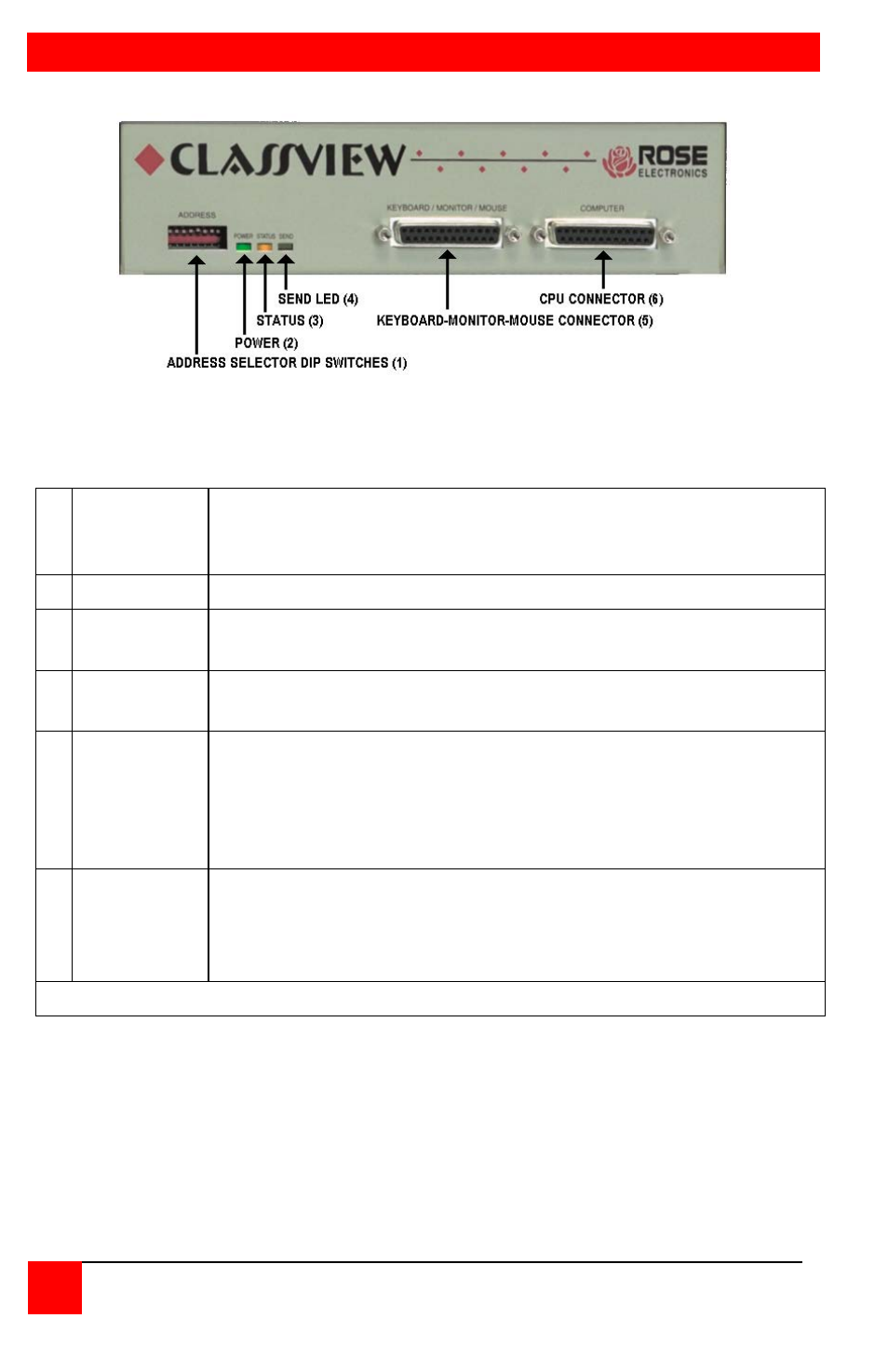
Figure 2. Front panel, model # CVT-CMB
1 Address
Defines the number of the CPU attached to the unit.
Address 0 is reserved for diagnostics. Address 255 is
reserved for the instructor's unit.
2 Power LED When lit indicates that unit is powered on.
3 Status LED
Flashes once a second to show bus connection. Also
flashes when keyboard or mouse activity occurs.
4 Send LED
When lit unit is sending video over the coax bus, one or
more monitors may be receiving the video.
5
Keyboard-
Monitor-
Mouse
Connectors
Keyboard, monitor, and mouse are connected at this port
using a Keyboard-Monitor-Mouse adapter cable. The cable
has a DB-25 male at one end and appropriate connectors at
the other end, depending upon your video, keyboard, and
mouse type. Only one adapter cable is needed.*
6
CPU
Connector
Your computer is connected at this port using a CPU adapter
cable. The cable has a DB25 male at one end and
appropriate connectors at the other end, depending upon
your video, keyboard, and mouse type.*
* See Appendix F and G for further cable information
Table 1. The front panel