Repair kits, Assembly instructions, Disassembly instructions – Precision Medical Continuous Intermittent Vacuum Regulator User Manual
Page 7
6
CONTINUOUS INTERMITTENT
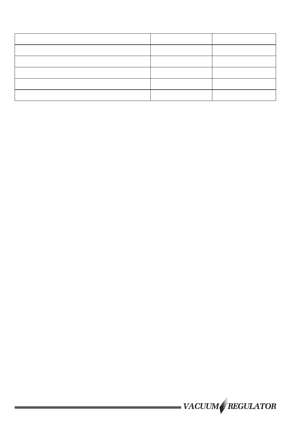
REPAIR KITS
Analog Part#
Digital Part#
PM3300 / PM3300D Vac Reg
RK6300
RK6300D
PM3300HV / PM3300DHV Vac Reg
RK6300HV
RK6300DHV
PM3300E / PM3300DE Vac Reg
RK6300E
RK6300DE
PM3300EHV / PM3300DEHV Vac Reg
RK6300EHV
RK6300DEHV
PM3400 / PM3400D Vac Reg
RK6400
RK6400D
PM3400E / PM3400DE Vac Reg
RK6400E
RK6400DE
ASSEMBLY INSTRUCTIONS
1. To assemble, perform the “DISASSEMBLY INSTRUCTIONS” in
reverse order.
NOTE:• Ensure the Selector Assembly is inserted with the groove in
the 12 o’clock position.
• Ensure tabs and slots on various components are properly
aligned and engaged when reassembling.
2. Lubricate all O-rings and cavities with Vacuum grease (part# 1775)
supplied in the Vacuum Regulator Repair Kit.
3. Repeat steps 1 through 3 of “OPERATING INSTRUCTIONS”.
4. Prior to returning Vacuum Regulator to service verify accuracy of gauge.
DISASSEMBLY INSTRUCTIONS
(Reference “PARTS DESCRIPTION”)
1. Loosen the Set Screw (Item # 11) in Selector Knob.
2. Pull the Control Knob Assembly (Item # 12) away from case. (The Regulator
Module (Item # 10) is threaded onto the Control Knob Assembly.)
3. Remove the screws (Item # 2) from the back of the product.
4. Remove the Rear Case (Item # 14) by pulling away from product.
5. Remove screws (Item# 2) from the top of the Timing Module.
6. Remove the Timing Module (Item# 13) by pulling away from the
Housing Assembly (Item# 1).
7. Separate the Case Assembly (Item# 9) by pulling it away from the
Housing Assembly (Item# 1).
8. Remove the Selector Assembly (Item# 6) by pulling it away from the
Housing Assembly (Item# 1).
9. Remove the Gauge Assembly (Item# 3).