MEDC CU1 User Manual
Page 9
Replacement of the Xenon Tube:
CAUTION:
Before removing the cover assembly, ensure that the power to the unit has been isolated
Unscrew the socket set screw (2mm A/F hexagon key) in the lens cover three full turns. Unscrew and remove the
lens cover.
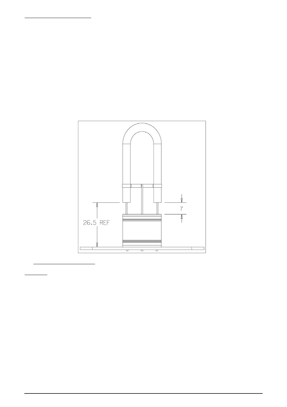
Remove the old tube by unscrewing the tube terminal block screws. The replacement xenon can now be fitted in to
the terminal block provided. If the replacement tube has a flexible trigger wire, ensure the tube is fitted into the
terminal block in the same orientation as the original tube.
Note:
the legs of the replacement tube may need to be trimmed to allow the tube to be positioned at the correct
height from the terminal block. See diagram below:
Once the required adjustments have been made, replace the cover using the same procedure as above but in the
reverse manner. Care must be taken to avoid damage to the threads and mating faces of the cover and
enclosure. Ensure the o-ring is correctly seated on the cover and that the cover is screwed down tightly such that the
maximum gap between the cover and enclosure is 0.2mm. Ensure the socket set screw in the cover assembly is
fully tightened to secure the cover assembly on the body.
6.0 CERTIFICATION/APPROVALS
IECEx units
Certified to IEC60079-0, IEC60079-1 and IEC60079-7
Ex de unit (IEC certification No. IECEx BAS 11.0149X)
CU1-S - Ex de IIB T4 (-50°C to +50°C) Gb
CU1-H - Ex de IIB T4 (-50°C to +70°C) Gb
The IECEx certificate and product label carry the IECEx equipment protection level marking
Gb
Where Gb signifies suitability for use in a Zone 1 surface industries area in the presence of gas.
© MEDC 2014
09/14