MEDC CU1 User Manual
Page 4
Access to Terminals
Unscrew the 3 off M5 screws (4.0mm A/F hexagon key) holding the cover assembly to the base. The screws are
retained in the cover. Remove cover to gain access to the interior of the terminal chamber.
Once termination is complete, carefully replace the cover back onto the enclosure, avoiding damage to the mating
surfaces. Evenly tighten the 3 off M5 screws (4.0mm A/F hexagon key) in the cover, ensuring the
4.0 OPERATION
The operating voltage of the unit is stated on the unit label.
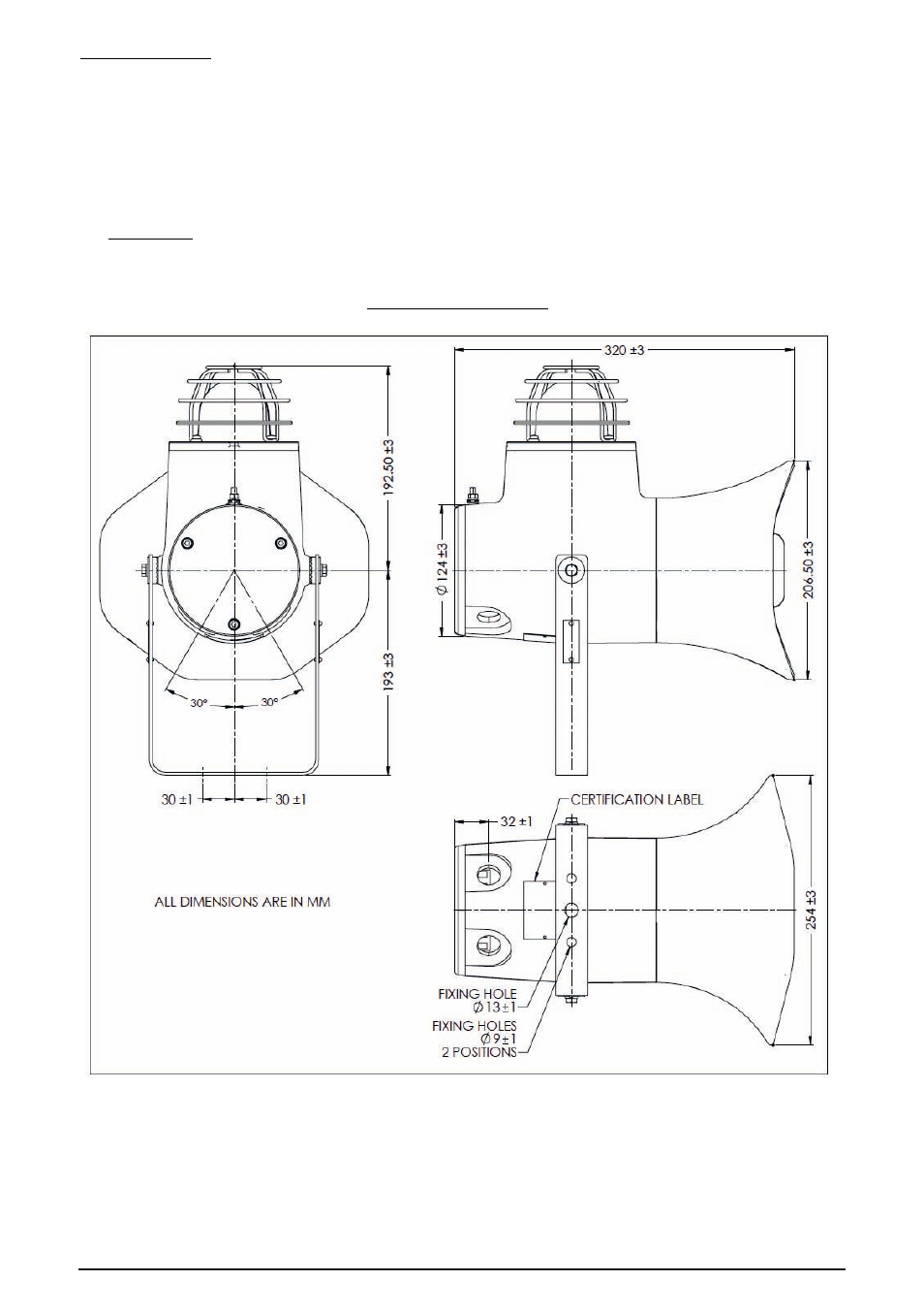
GENERAL ARRANGEMENT
maximum torque
value for the cover screws is observed, as marked on the Ex e cover. Ensure the O-ring is correctly seated in its
groove during re-assembly.
09/14
© MEDC 2014
See also other documents in the category MEDC Sensors:
- PB (8 pages)
- PB (32 pages)
- PB (24 pages)
- BG3 (8 pages)
- BG2 (12 pages)
- PB (12 pages)
- PH1 (20 pages)
- PH1 (8 pages)
- PAS1 (4 pages)
- SM87BG (28 pages)
- SM87BG (28 pages)
- XB13 Flashing Beacon (8 pages)
- SM87HXB (28 pages)
- FB11UL (4 pages)
- Expertline (16 pages)
- FB11 (20 pages)
- FB12 (20 pages)
- XB4 (24 pages)
- FB15 (4 pages)
- FB15 (16 pages)
- FL12 (20 pages)
- FL11 (20 pages)
- SM87 LU3 (24 pages)
- LD15 (32 pages)
- XB12 (20 pages)
- XB11 (24 pages)
- SM87LED (20 pages)
- XB10 (20 pages)
- XB12 (20 pages)
- XB13 (2 pages)
- XB15 (24 pages)
- XB15 (32 pages)
- XB16 (8 pages)
- XB9 (16 pages)
- XB8 (20 pages)
- dSLB 20 (4 pages)
- dSLB 20 LED (8 pages)
- DB1 (8 pages)
- PAS2 (4 pages)
- PAS2 (4 pages)
- DB1 (20 pages)
- HD1 Range (4 pages)
- HD1 Range (24 pages)
- JB11 (4 pages)