MCZ Hydrotherm 70 User Manual
Page 32
INSTALLATION AND USE MANUAL
Chapter 4
page
32
Installation and assembly
Technical service – MCZ GROUP S.p.A. all rights reserved - Reproduction prohibited
Installing a funnel with anti-reflow air intakes on the discharge pipe of
the valve. The diameter of the connection pipe between the funnel and
the discharge network must be at least double the diameter of the
valve.
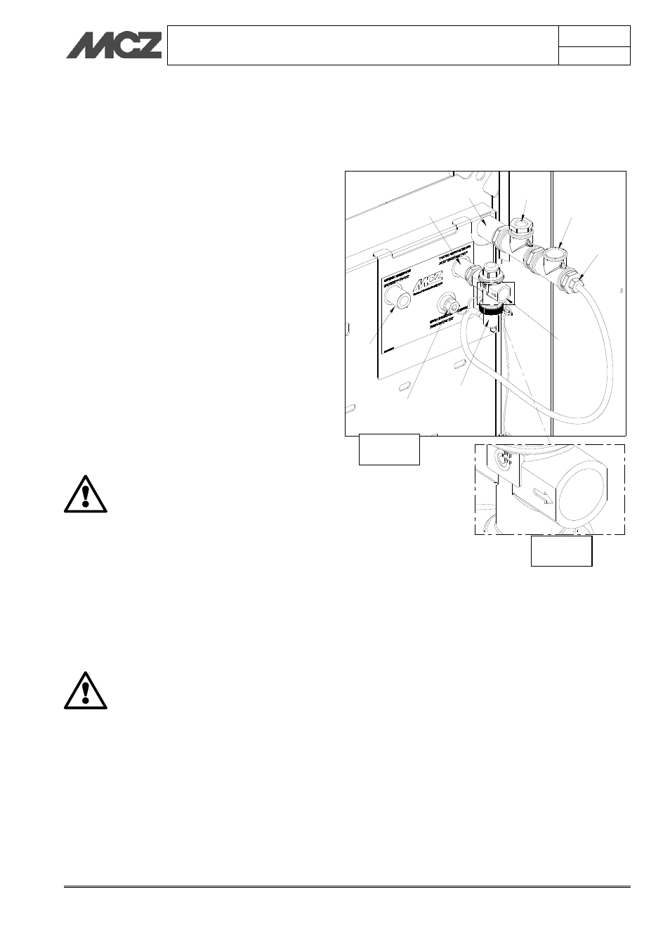
1. Aqueduct intake F 1/2”
2. Thermal safety discharge valve attachment F1/2”
3. Thermal safety discharge valve F 3/4”
4. Attachment for discharge duct F 3/4”
5. Boiler water outlet F 3/4”
6. Control unit well probe F 1/2"
7. Delivery to the system F 3/4"
8. Thermal safety discharge valve probe M 1/2”
9. Combustion adjuster bulb
4.8.4. Maintenance
In the lower part of the valve a red button is located that lets you
perform the purging operations and check the function. It is necessary
for a technician check the function of the valve at least once a year.
4.8.5. Safety
MCZ SHALL NOT BE HELD LIABLE FOR ANY DAMAGE
TO PERSONS OR OBJECTS DUE TO INCORRECT
CONNECTIONS, DUE TO THE INSTALLATION OF A
VALVE NOT CORRESPONDING TO THE MODEL
ADVISED OR IMPROPER USE OF THE DEVICE.
The installation of the thermal safety discharge valve must be carried
out by qualified technical personnel according to the instructions
reported in this manual and in accordance with current standards.
If the valves are not installed, calibrated and maintained correctly
according to the instructions contained in this manual, they may not
function correctly and may place the user in danger. Ensure that all the
connection fittings are hydraulically sealed. In creating the hydraulic
connections, pay attention not to mechanically over stress the thread of
the valve body. In time it is possible that breakages may occur with
ATTENTION: assemble the thermal safety discharge
valve respecting the direction of the arrow, as in the
figure to the side.
1
2
3
4
5
6
7
8
9
Fig.d
Fig.e