Hydraulic diagrams, Diagram 1 open tank (kit 1 open tank) – MCZ Hydrotherm 70 User Manual
Page 25
INSTALLATION AND USE MANUAL
Chapter 4
page
25
Installation and assembly
Technical service – MCZ GROUP S.p.A. all rights reserved - Reproduction prohibited
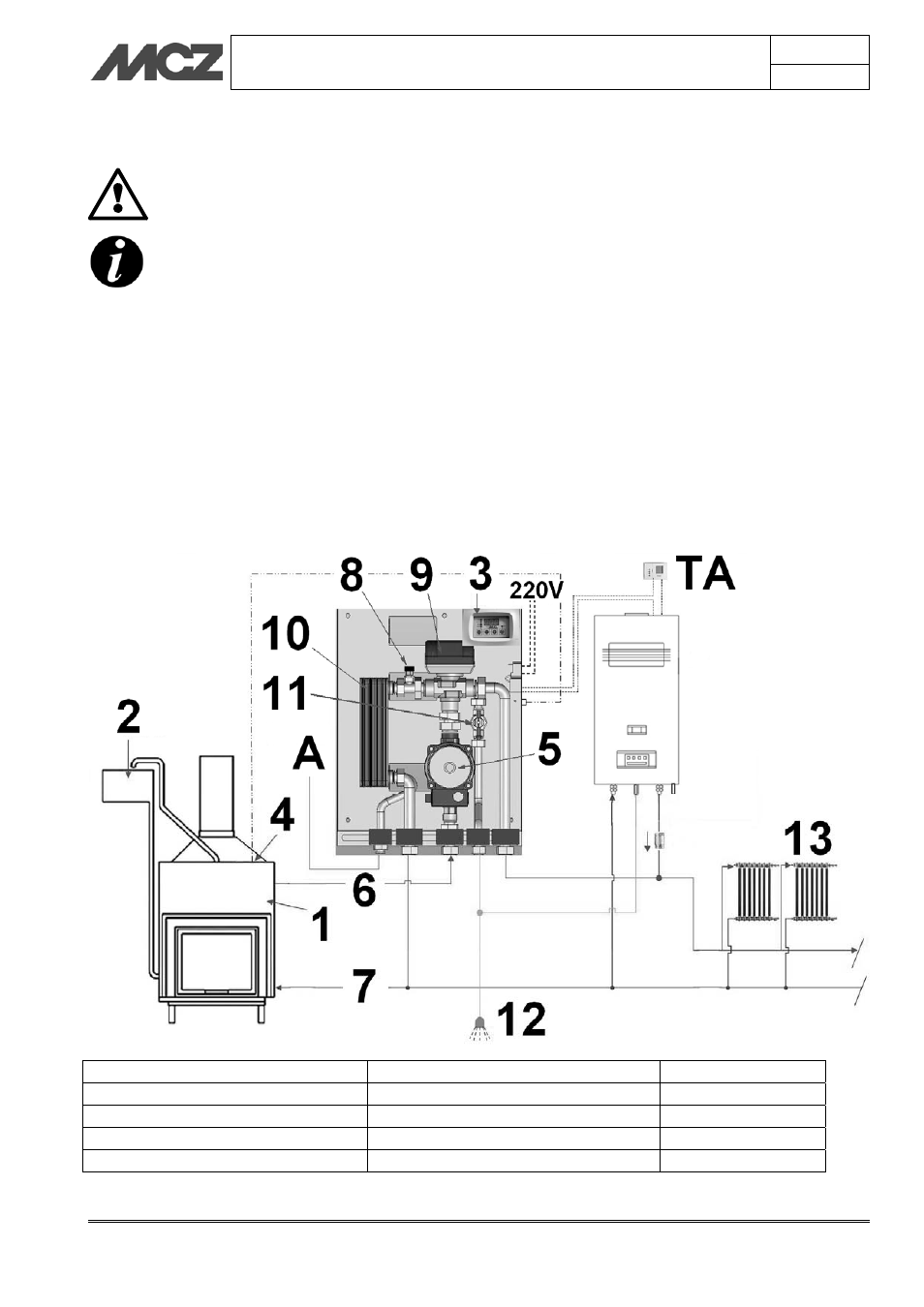
4.7. HYDRAULIC DIAGRAMS
The distance of the hydraulic kit, as stated in the
diagrams below within the speckled area, from the
fireplace stove must not exceed 1 metre.
The following diagrams are to be used only as a guideline.
For proper connection, follow the notes and the instructions
of the plumbing and heating installer, in compliance with
regulations in force.
4.7.1. Diagram 1 OPEN TANK (KIT 1 OPEN TANK)
DESCRIPTION: Fireplace stove as the only heat source with production of domestic hot water (DHW).
ACTIONS:
- fireplace stove heating;
- domestic hot water with fireplace.
1-Fireplace stove
6-Delivery circuit
11-Flow switch
2-Open expansion vessel with float
7-Return circuit
12-Domestic water
3-Control unit
8-Automatic vent valve
13-Radiator
4-Temperature probe
9- 3-way valve
A- Aqueduct
5- Circulator
10 - Domestic hot water exchanger
TA-Room thermostat