Ducts for kit vf 180 m, H (airsystem b70), Fireplace stove with forced ventilation 4.7.2.1 – MCZ AirSystem 70 DX User Manual
Page 19
Chapter 4
INSTALLATION AND USE MANUAL
page
19
Installation and assembly
Technical service – MCZ S.p.A. all rights reserved - Reproduction prohibited
4.7. EXTERNAL AND INTERNAL AIR INTAKE
4.7.1. Fireplace stove with natural ventilation
If the fireplace stove is installed with natural ventilation, i.e. with no
electric fan, make an external combustion air intake of 300 cm² net
behind the unit so that fresh air always flows beneath the fireplace
stove.
(figure 7)
You must comply with this instruction fully, because otherwise a lack of
oxygen may compromise combustion and calorific energy of the
product.
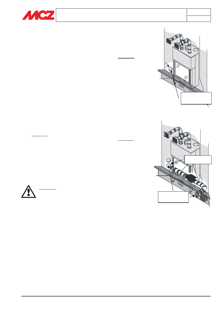
4.7.2. Fireplace stove with forced ventilation
4.7.2.1.
Ducts for kit VF 480-620 m
3
/h
If the fireplace stove is installed with forced ventilation, i.e. using a fan
of 480 or 620 m
3
/h, place air intakes and ducts as follows:
for proper air circulation in the room, it is advisable to connect one
of the two ducts to the exterior of the home, creating an air intake
of 150 cm², in order to draw in clean, fresh air; place the other in
the room where the fireplace stove is installed (also of 150 cm²).
This mode allows a proper mix of the air in the room of installation
and better cooling of the structure of the fireplace stove.
(Figure 8)
If you cannot make this kind of connection, you will still need to
connect both ducts, whether they are both directed to the exterior or
the interior. Depending on the selection, you will have operating
temperatures that are slightly above or below average but which do not
compromise proper operation of the product.
ALWAYS CONNECT THE TWO DUCTS AND RUN THEM
OUTSIDE THE CLADDING OF THE FIREPLACE STOVE.
IF THIS DIRECTIVE IS NOT OBSERVED, THE FAN,
HAVING GREATER STATIC PRESSURE, MAY ALSO
INTAKE AIR INTENDED FOR THE FRONT GRILLE OF
THE FIREPLACE STOVE AND REQUIRED FOR
COMBUSTION
4.7.2.2.
Ducts for kit VF 180 m
3
/h (Airsystem B70)
Differently from the kit VF 480-620 m
3
/h, the kit VF 180 m
3
/h does not
require ducts, since the lower power of the fans and their position
with respect to the fireplace stove allow proper operation of the system
provided a considerable quantity of air is provided under the unit.
Considering that this type of fireplace is normally set in an internal wall
of the home and it is almost never possible to provide ducts to the
outside of the home as with the previously described model, the
ventilation air must all be drawn from the room of installation, using the
air intakes on each side of the cladding
It is necessary to provide two air intakes with a net minimum section
of 150 cm
2
on both sides of the cladding that allow a continuous
exchange of oxygen under the fireplace stove
(figure 9).
Figure 7 – Intake for external combustion air
and for natural ventilation
Figure 8 – Air intakes for ducts of fan and
combustion air intake.
Air intake of 300 cm
2
for
combustion air and natural
convection
Internal and external air
intakes of 150 cm
2
for forced
ventilation air.
Combustion air intake of
150 cm
2