Rear panel features, Vg a d is tr ib ut io n a mp lif ie r, Through-desk mounting – Extron electronic P/2 DA4xi User Manual
Page 6
P/2 DA4xi/6xi • User’s Guide
P/2 DA4xi/6xi • User’s Guide
P/2 DA4xi and P/2 DA6xi, cont’d
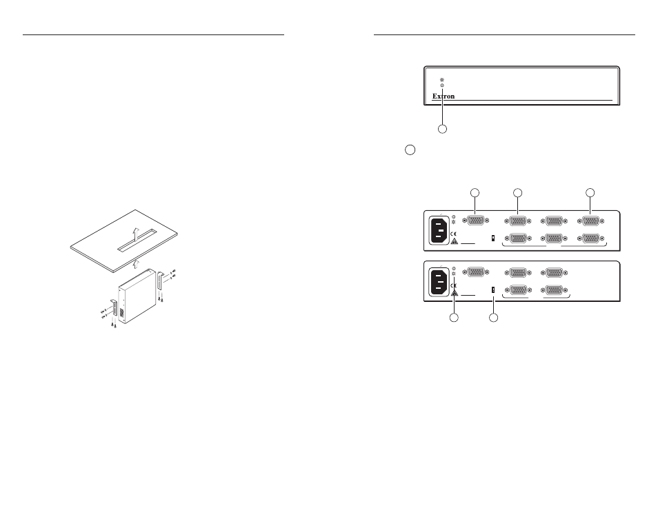
Front panel indicators
VGA DISTRIBUTION AMPLIFIER
1
1
Power LED
: A green LED indicates that the distribution
amplifier is receiving power.
Rear panel features
100-240V 0.2A
INPUT
P/2 DA6xi
VIDEO GAIN
1V
.7V
3
(LOCAL MONITOR)
2
1
3
5
4
6
OUTPUTS
50/60 Hz
100-240V 0.2A
INPUT
P/2 DA4xi
VIDEO GAIN
1V
.7V
3
(LOCAL MONITOR)
2
1
3
4
OUTPUTS
50/60 Hz
P/2 DA4xi
P/2 DA6xi
1
2
3
4
5
a
Power LED
— A green LED indicates that the distribution
amplifier is receiving power.
b
Video Gain sliding switch
— Used for installations with long
output cable runs, the 1.0 V (up) position gives a brighter
picture. The default Video Gain setting is 0.7 V (down).
c
Input connector
— Connect the input cable (using VGA-UXGA
signals) to the DA’s 15-pin HD female connector.
d
Local Monitor connector
— Connect a local monitor to this 15-
pin HD female connector for loop-through capability.
e
Output connector
— Connect the output device to the 15-pin
HD female connector.
Through-desk mounting
The P/2 DA4xi/6xi can be mounted using the optional
through-desk mounting brackets (Extron part #70-077-02).
1.
Attach the mounting brackets to the DA with the screws
provided (shown below).
2.
Cut the proper sized hole in the mounting surface.
3.
Hold the DA with the attached brackets against the
underside of the table or other furniture. Mark the location
of the screw holes of the bracket on the mounting surface.
4.
Drill 3/32" (2 mm) diameter pilot holes, 1/4" (6.3 mm)
deep in the mounting surface at the marked screw
locations.
5.
Insert four #8 wood screws through the bracket and into
the four pilot holes. Tighten all four screws to secure the
DA in place.
VG
A D
IS
TR
IB
UT
IO
N A
MP
LIF
IE
R
5
4
P/2 DA4xi/6xi • User’s Guide